
User Manual
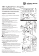


18820 Table-style keyboard stand
»Omega Pro«
- a slim yet high-strength tubular steel construction
- uncomplicated, graduated height adjustment
- individually positionable support arms – according to width of keyboard
- foldable legs for flat packaging - ideal for mobile use
- design matches keyboard benches 14080, 14085 and 14086
- optional attachments 18811 (2nd level) and 18822 (3rd level) are available
- for more mounting options see chapter: TECHNICAL DATA
- max. load: 80 kg including additions
- base w x d 975 x 575 mm, height 600-1020 mm,
- supports w x d max. 790 x 345 mm
SAFETY INSTRUCTIONS
1. COMPONENTS
2. ASSEMBLY
Thank you for choosing this product. This instruction manual informs you about the
important steps to set up and handle the product. We recommend to keep the manual
in a separate place for a possible later use.
GENERAL
- The possibility to adjust the product involves entrapment hazards. Therefore careful
- and thoughtful handling during installation, operation, dismantling and maintenance
- is essential.
- Protect the stand from adverse external conditions (moisture, wind, shocks).
- The careful and diligent treatment preserves the functionality,
- durability and ensures last not least safety.
- Faulty products are not to be used; damaged parts must be replaced or repaired
- before handling
OPERATION
- Maximum load 80 kg (including additions)
- Ensure that the subsurfaces are stable and even
- The locking bolt of both clamping screws must always be engaged
- Always remove the keyboards before you adjust the height
- The maximum height is reached as soon as the STOP mark on the stand tube
- becomes visible (see chapter HEIGHT ADJUSTMENT)
- both tubes must always be adjusted to the same height
- The long side of the supports must point in the direction of the long base sides
- Screw connections must be firmly tightened
SET-UP INSTRUCTIONS
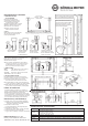
1. COMPONENTS
a U-bracket, foldable, b base tubes complete (2x), c support arms complete (2x), k carrying strap
Accessories bag:
d rubber pads ø 20 x 5 mm (4x), e carriage bolt M6 x 65 mm (2x), f washer ø 6,4 mm (2x),
g wing nut M6 (2x), h clamping screw with logo (2x), i clamping screw without logo (2x)
j Velcro / cable tie (4x)
2. ASSEMBLY
STAND (2.1-2.4)
2.1 Unfold both stand tubes of the u-bracket a all the way to the stop.
WARNING! During this procedure there is entrapment hazard in area Q.
It is therefore essential that you keep your limbs, clothing and other things
out of the area. This also applies to third parties.
2.2 Screw the clamping screws i into the threaded bushings of the upper corners and
2.2 make sure that the locking bolts are immersed in the boreholes of the stand tubes.
2.3 Insert the base tubes b into the stand tubes...
2.4 ...and by screwing the clamping screws h fix their (equal) height.
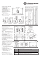
SUPPORT ARMS (2.5-2.7) (see also Chapter 6 - SETTINGS)
2.5 We recommend symmetrical mounting of the two support arms.
2.6 The long side of the support must point in direction of the long base tube.
2.7 Insert carriage bolt e through the support c and the desired borehole of
2.7 the u-bracket and screw together with washer f and wing nut g.
ACCESSORIES (2.8-2.11)
2.8 RUBBER PROTECTIVE LAYERS d are self-adhesive and can when needed
be placed c on the desired position of the support – e.g. if the depth of the
instrument is too small to cover the two large rubber protectors.
2.9 VELCRO STRAPS j keep the wiring tidy. Velcro straps can be placed at random.
Merely thread, tighten and press together.
The straps can be removed easily. It is also possible to shift the straps along the tubes.
2.10 Velcro straps are also used to secure the folded tubes.
2.11 The CARRYING STRAP k is a welcome help when transporting the keyboard table.
Procedure: - place the keyboard table on the support arms c
Procedure: - fold the legs
Procedure: - hook in both Karabiners into the boreholes (A or B)
FOLDING FUNCTION & TRANSPORT (2.12-2.14)
Turn the keyboard table over and place it on the support arms c
2.12 Loosen tightened clamping screw i approx. one turn
2.13 Pull handle (= unlock bolt) and hold, now retract base.
2.14 RECURRING UNFOLDING: first remove the CARRYING STRAP 2.11 and the VELTRO STRIP 2.10;
afterwards pull and hold handle (i), swing open the legs (90°), tighten clamping screw i.
2.10
The unfolding of the legs
during transport is preven-
ted by securing them with
at least one Velcro strip
around both legs.
2.14
NOTE:
The thread of the
clamping screw (i) must
not protrude in the inside
of the pipe, otherwise the
foot does not fully unfold.
In this case turn back the
clamping screw as far as
necessary.