
Installation Sheet

INSTALLATION INSTRUCTIONS
For item#P1566-729 (New. 2020/9/29)
READ AND SAVE THESE INSTRUCTIONS
W A R N I N G ! S H U T P O W E R O F F AT F U S E O R C I R C U I T B R E A K E R .
AVERTISSEMENT! COUPER LE COURANT AU NIVEAU DES FUSIBLES OU DU DISJONCTEUR.
Fig.
Fig. 2
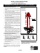
PREPARING FOR INSTALLATION (Fig. 1)
1. Shut off power at the fuse box or circuit breaker box
and remove the old fixture including the mounting
hardware.
2. Carefully unpack your new fixture and lay out all the
parts in a clean area. Take care not to misplace any
small parts necessary for installation.
3. Secure rod (J) onto the all thread (I) on the fixture body.
4. Determine the desired hanging height and thread rods
(F1, F2 and F3) to the all thread on rod (J). Screw loop
(H1) onto rod (F1). Pass the wires carefully through
each rod as you assemble.
5. Attach the quick link (G) to loop (H1) and loop (H2) on
the canopy (E). Carefully feed the wire through loop
(H1), quick link (G), and loop (H2).
6. Loosening screws (K) to remove the mounting plate (C)
from canopy (E). Positioning the mounting plate (C) on
the ceiling and mark location of the two mounting holes
for the plastic anchors (A). Drill the appropriate size
holes on the ceiling and insert the plastic anchors (A).
7. Attach the mounting plate (C) to the junction box, not
included, using mounting screws (B) (Size:
#8-32N*L0.5”). The side of the mounting plate marked
“GND” must face out.
8. Secure the mounting plate (C) by screwing wood
screws (D) through the holes on the mounting plate into
the plastic anchors (A).
CONNECTING THE WIRES (Fig. 2)
9. Connect the electrical wires as shown in figure 2,
making sure that all wire connectors are secured. If
your junction box has a ground wire (green or bare
copper), connect the fixture’s ground wire to it.
Otherwise, connect the fixture’s ground wire directly to
the mounting plate (C) using the green screw provided.
10. Tuck the wire connectors neatly into the junction box.
COMPLETING THE INSTALLATION (Fig. 1)
11. Place canopy (E) over the mounting plate (C) and
secure it with screws (K).
12. Install (6) six G9 xenon bulbs (P) (included) up to 60
watts each, or CFL or LED equivalent, in accordance
with the fixture specification—DO NOT EXCEED THE
MAXIMUM WATTAGE RATING! (NE PAS DEPASSER
LA PUISSANCE NOMINALE MAXIMALE!).
13. Place the glass shade (Q) over the socket and twist to
secure it to the socket cup (O).
14. Align the holes of the metal ring (M) to the arm (N) and
secure with screws (L).
Your installation is now complete. Return power to the junction
box and test the fixture.
Note: Illustration (Fig. 1) on this manual is for installation
purposes only. It may or may not be identical to the fixture
purchased.
LA-3291E
FIXTURE
WIRES
Black or
Smooth
HOUSE
WIRES
Black
(Hot)
FIXTURE
WIRES
White or
Ribbed
HOUSE
WIRES
White
(Neutral)
FIXTURE
WIRES
Bare
Copper
(Ground)
HOUSE
WIRES
Green
(Ground)
Set#A-021-290119
- Mounting Plate
- Ground Screw
- Mounting Screw*2
Rod#W30-1-66*2(F1)
W30-1-66*4(F2)
W30-H-66*2(F3)
IMPORTANT: FIXTURE SHOULD BE INSTALLED BY
A QUALIFIED ELECTRICIAN TO ENSURE PROPER
WIRING AND INSTALLATION.
A
C
D
B
E
K
F1
F2
F3
H1
H2
G
J
I
L
M
N
O
P
Q