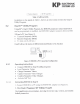
3.3.4 1.3.8 IK ELECTRONIC SYSTEMS LTD The Fujitsu MB1501 series chip contains » 11 GHz two modulus scalper that can select either 64/65 or 128/129 divide ratio Corneal signal generator 16-bit shift register 15-bit latch i~bit switch counter Flier comparative Charge pinup vital oscillator 19-bit shift register $8-bit Jamel Programmable divider This chip has major electrical characteristics: the power supply current typ. min 15mA, Veo +5V, Vp 18V, ENERGIZER The synthesizer uses a 12.
3.4 3.5 ELECTRONIC SYSTEMS LUD | Feedback Buffer Amplifier The feedback buffer amplifier, MARTS, provides isolation from the goad to the input & Fin of the MORRIS © a Power Supplies The feeling voltage levels are necessary for major blocks of he BERING: +12.5 Vb for the output power amplifier, the driver and antenna switch feeds. Terr The driver and delivered feeds. F3Y for the digital block, modulator chip, and active audio filter supply.
of or pee 4.2 4.3 ELECTRONIC SYSTEMS LTD Date, and Load Enable signals on pins 9,30, and 11 of the MBG chip. it w the Sock detection signal to determine phase comparative output. Rhea level on its por is low, the phase Is locked. While the phase difference of Fr and Ip exists, the putout level goes high. The PIT] external signal is used to configure the T/Bx modes. 1 the FIT elev is #0," Tx mode is active. When the pock Detector bus is “0.
de 12 JEN BP Icon SYSTEMS LTD { Synthesizer BVS sense 508 V Cos of RE and TX BYY sense ~ SDV Driver & Driver 5.7VR sense ST For diagnostic and repair purposes, the BSK bas a diagnostic mode. The diagnostic mode is disabled by fandango, ut can be a agnostic mode enables BER bio the Micro to LOW ate by tripping P2.7 analyzed separately, using special PC Software for technicians.
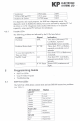
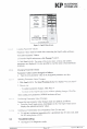
S212 5.2.15 £4 5.3 K ELECTRONIC SYSTEMS LID Rid Faded 435. iE Ignition Bistro GLY TES rf Ben Pimiento ff WE, TBO | my i FECES Figure 5: Gull Main Screen t spading Parameter Values Parameter values must be loaded after connecting the Guppy utility so {tare. Ta Lewd Parameter Vale 1. From the Guppy main screen, chick Prompt 7 (Alt P). ek Read (Alt 1). The name of the device (ype.
K ELECTRONIC SYSTEMS LTR GOT parameter, ate at To view a brief explanation of any BER] appear in the design la nation, displays e Sereneness click the required parameter ext box. The cursor will feet bo, and the valid parameter range, with brief exp) the bottom of the screen.
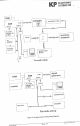
WK ELECTRONIC SYSTEMS LTD» Manufacturer Testing Setup Diagram Measuring and Auxiliary Equipment To make the necessary calibrations, according to the regulations for BERIBERI, iris necessary 1o use the fallowing meas ing and auxiliary equipment s Spectrum analyzer Oscilloscope Signal generator Sin adder Multi meter DC power supply 12.
ELECTRONIC SYSTEMS LTD bem I a Tas Pe watermelon pL vane soon refer J power fr lr spore [PT hee i I ee Popsicle . WEER | Tx mode setup i pone Cnt | supply 030 piston f j— counter ROI) fluoroscopic I” Ric .