Kramer Electronics, Ltd.
Contents Contents 1 2 2.1 3 4 5 5.1 5.2 6 6.1 6.2 6.3 6.
Introduction 1 Introduction Welcome to Kramer Electronics! Since 1981, Kramer Electronics has been providing a world of unique, creative, and affordable solutions to the vast range of problems that confront the video, audio, presentation, and broadcasting professional on a daily basis. In recent years, we have redesigned and upgraded most of our line, making the best even better! Our 1,000-plus different models now appear in 11 groups1 that are clearly defined by function.
Getting Started 2.1 Quick Start This quick start chart summarizes the basic setup and operation steps.
Overview 3 Overview The Kramer FC-8 is a serial-to-wireless and wireless-to-serial LAN device server that acts as a bridge for connecting serial devices to an 802.11b/g wireless LAN. The FC-8 supports TCP/UDP sockets, a Web server with Web site, and WEP, WPA, WPA2 Wi-Fi encryption. The FC-8 is housed in a Kramer TOOLS enclosure, and is powered by a 12V DC power supply.
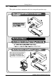
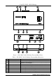
Your FC-8 Wi-Fi - RS-232 Bridge Figure 1: FC-8 Wi-Fi - RS-232 Bridge Front and Back Views Table 1: FC-8 Wi-Fi - RS-232 Bridge Front and Back Functions 1 2 # Feature 12V DC Connector FACTORY RESET Button 3 4 5 6 7 8 RS-232 DB-9F Port WI-FI Antenna LINK LED TX LED RX LED ON LED 4 Function +12V DC for powering the unit When pressed, erases all configuration data. Use only under the guidance of Kramer Technical Support.
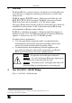
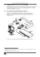
Connecting the FC-8 Wi-Fi - RS-232 Bridge 5 Connecting the FC-8 Wi-Fi - RS-232 Bridge The FC-8 can be used to wirelessly control an RS-232-based device from a PC via an ad-hoc network (see Figure 2) or via an access point (router) to a larger network or the Internet (see Figure 3). 5.
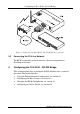
Configuring the FC-8 Wi-Fi - RS-232 Bridge Figure 3: Connecting the FC-8 Wi-Fi - RS-232 Bridge (Access Point) 5.2 Connecting the FC-8 to a Network The FC-8 is connected to the network by software configuration as described in Section 6. 6 Configuring the FC-8 Wi-Fi - RS-232 Bridge This section explains how to configure the FC-8 and the host system for operation. The section includes: Using the Default Network Configuration, see section 6.1 Configuring the Host System, see section 6.
Configuring the FC-8 Wi-Fi - RS-232 Bridge 6.1 Using the Default Network Configuration The FC-8 is configured in the factory with the following default configuration that can be used immediately in an ad-hoc network: Table 2: FC-8 Default Network Configuration Parameter Network Name IP Address Subnet Mask Mode Port 6.2 Value !Kramer-FC8 (ad hoc network) 192.168.3.2 255.255.255.
Configuring the FC-8 Wi-Fi - RS-232 Bridge Figure 4: Wireless Network Connection Window 5. If the Kramer-FC8 network does not connect: Click on Kramer-FC8 to open the network and click Change Advanced Settings. Choose to highlight Internet Protocol (TCP/IP) and click Properties. Make sure Obtain an IP address automatically is selected. 6. Begin operating the device as described in section 7 or if necessary, change the FC-8 configuration as described in section 6.3. 6.
Configuring the FC-8 Wi-Fi - RS-232 Bridge To change the FC-8 configuration, do the following: 1. In the Internet browser of a PC attached to the FC-8 network, enter the IP address of the FC-8 (for example, using the default IP address: 192.168.3.2). The Serial Net setup page appears (see Figure 5). Table 3 explains the fields.
Configuring the FC-8 Wi-Fi - RS-232 Bridge Table 3: FC-8 Serial Net Configuration Parameters Parameter MAC Address Bootblock Version Serial Number Possible Values Web Server Status Message Must be I/OK Firmware Version Must end with b17 or above Hardware Version Active IP Address Subnet Address IP Gateway Wireless LAN SSID IP Registration Host Server Name 192.168.3.2 (Default) 255.255.255.0 (Default) 0.0.0.
Configuring the FC-8 Wi-Fi - RS-232 Bridge Parameter Wireless LAN WEP Key1 Wireless LAN WEP Key2 Wireless LAN WEP Key3 Wireless LAN WEP Key4 Pre-shared Key Passphrase SerialNet Serial Parameters Default IP Possible Values WEP64 – no more than 10 characters (5 bytes) allowed (hex 0-9 A-F) WEP128 – no more than 26 characters (13 bytes)allowed (hex 0-9 A-F) Same as WEP Key1 Same as WEP Key1 Same as WEP Key1 WPA – ASCII string must be between 8-63 alphameric characters 5, 8, N, 1, 0 (Defaul
Operating the FC-8 3. After submitting the new parameters, reset the FC-8 by clicking the Reset iChip link at the bottom of the window. The new window with the message “iChip is performing reset” opens. Wait about 1 minute and close this new window. Note: To start using the new settings, disconnect the wireless connection from the FC-8 and reconnect it again with new parameters.
Technical Specifications 8 Technical Specifications The FC-8 technical specifications are shown in Table 5: 1 Table 5: FC-8 Technical Specifications INPUT: OUTPUT: HARDWARE DESCRIPTION: RS-232 DB9F connector Antenna Core CPU: 32-bit RISC ARM7TDMI, low-leakage, 0.
14
For the latest information on our products and a list of Kramer distributors, visit our Web site: www.kramerelectronics.com where updates to this user manual may be found. We welcome your questions, comments and feedback. Safety Warning: Disconnect the unit from the power supply before opening/servicing. Caution Kramer Electronics, Ltd. Web site: www.kramerelectronics.com E-mail: info@kramerel.