K R A ME R E LE CT R O N IC S L TD .
Contents 1 Introduction 1 2 2.1 2.2 2.3 3 Getting Started Achieving the Best Performance Safety Instructions Recycling Kramer Products Overview 2 2 3 3 4 4 Defining the RC-43T Remote Controller 5 5.1 5.2 5.3 Connecting the RC-43T K-NET Wiring Terminating the K-NET Bus Installing the Configuration Software 10 11 12 12 6 6.1 6.
1 Introduction Welcome to Kramer Electronics! Since 1981, Kramer Electronics has been providing a world of unique, creative, and affordable solutions to the vast range of problems that confront the video, audio, presentation, and broadcasting professional on a daily basis.
2 Getting Started We recommend that you: Unpack the equipment carefully and save the original box and packaging materials for possible future shipment Review the contents of this user manual i Go to http://www.kramerelectronics.com/support/product_downloads.asp to check for up-to-date user manuals, application programs, and to check if firmware upgrades are available (where appropriate).
2.2 Safety Instructions ! 2.3 Caution: There are no operator serviceable parts inside the unit Warning: Use only the power cord that is supplied with the unit Warning: Do not open the unit.
3 Overview The RC-43T is a remote control keypad with six touch-sensitive, backlit buttons. It is designed to be used in conjunction with room controllers, such as the SL-1. Using the Kramer K-Config software, each button on the RC-43T can be programmed on the room controller with a function, where each function can comprise multiple individual actions. The RC-43T is available in US and European versions. Throughout this manual the US version is used for illustrative purposes.
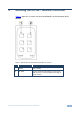
4 Defining the RC-43T Remote Controller Figure 1 shows the six, touch-sensitive, backlit buttons on the front panel of the RC-43T. Figure 1: RC-43T Remote Controller Front Panel US Version # Feature Description 1 Six Touch-sensitive Buttons Program the button functions on the connected room controller 2 Six LEDs Flashes yellow when the button is touched.
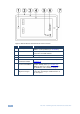
Figure 2: RC-43T Remote Controller Rear View US Version # 6 Feature Description 1 Mounting Holes Attach the RC-43T to the wall mounting box with the screws provided (see Section 6.2) 2 Front Panel Cosmetic panel that covers the PC Board and houses the removable buttons 3 PC Board Frame Mounting panel that houses the PC Board 4 PC Board 5 SW7 K-NET Termination Switch Use to set the K-NET bus termination (see Section 5.
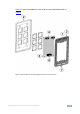
Figure 3 shows an exploded rear view using the same identification table as Figure 2.
Figure 4: RC-43T Remote Controller Front Panel EU Version # 8 Feature Description 1 Six Touch-sensitive Buttons Program the button functions on the connected room controller 2 Six LEDs Flashes yellow when the button is touched.
Figure 5: RC-43T Remote Controller Rear View EU Version # Feature Description 1 Mounting Holes Attach the RC-43T to the wall mounting box with the screws provided (see Section 6.2) 2 SW7 K-NET Termination Switch Use to set the K-NET bus termination (see Section 5.2) 3 KNET 4-pin Captivescrew Terminal Block Connect to a master room controller or to another auxiliary device (see Section 5.1). Note: The RC-43T is always device ID 2 on the K-NET bus.
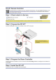
5 Connecting the RC-43T Figure 6: Connecting the RC-43T Remote Controller To connect the RC-43T as illustrated in the example in Figure 6: Connect the RC-43T to a room controller, (for example, the SL-1) via the K-NET 4-pin, (see Section 5.
5.1 K-NET Wiring The K-NET connector on the RC-43T must be connected to a room controller via a four wire cable as shown in Figure 7 and Figure 8. Figure 7: RC-43T K-Net Wiring US Version Figure 8: RC-43T K-Net Wiring EU Version Note: The RC-43T is always device ID 2 on the K-NET bus and cannot be changed.
Connect pin 3 on the K-NET connector to pin 3 on the room controller K-NET connector (B to B) Connect pin 4 on the K-NET connector to pin 4 on the room controller K-NET connector (G to G) 5.2 Terminating the K-NET Bus The devices at both ends of the K-NET bus must be terminated.
6 Installing the RC-43T Installing the RC-43T consists of the following steps: Installing the required buttons (see Section 6.1) Connecting the RC-43T to the room controller or other auxiliary devices (see Section 5.1) Programming the room controller for the RC-43T Note: Programming is covered by the K-Config User Manual and therefore not described here. 6.1 Installing the RC-43T in the wall mounting box (see Section 6.
6.2 Installing the RC-43T in the Wall Mounting Box Figure 11: Mounting the RC-43T in a Wall Box US Version To install the RC-43T in the wall mounting box: 1. Remove the front panel of the RC-43T. 2. Insert the RC-43T into the wall mounting box and secure it using the two M3 x 10mm screws supplied. 3. Replace the front panel of the RC-43T.
7 Technical Specifications PORT: 1 K-NET on a 4-pin removable terminal block POWER CONSUMPTION: 12V DC, 100mA OPERATING TEMPERATURE: 0° to +40°C (32° to 104°F) STORAGE TEMPERATURE: –40° to +70°C (–40° to 158°F) HUMIDITY: 10% to 90%, RHL non-condensing DIMENSIONS: US: 6.9cm x 1.6cm x 11.4cm (2.72" x 0.63" x 4.5") W, D, H EU: 8.6cm x 1.6cm x 8.6cm (3.39" x 0.63" x 3.39") W, D, H 8.0cm x 1.6cm x 8.0 cm (3.15" x 0.63" x 3.15") W, D, H WEIGHT: 0.3kg (0.66lbs) approx.
For the latest information on our products and a list of Kramer distributors, visit our Web site where updates to this user manual may be found. We welcome your questions, comments, and feedback. Web site: www.kramerelectronics.com E-mail: info@kramerel.