
Owner's manual

6
RC-43T - Defining the RC-43T Remote Controller
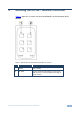
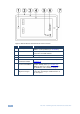
Figure 2: RC-43T Remote Controller Rear View US Version
#
Feature
Description
1
Mounting Holes
Attach the RC-43T to the wall mounting box
with the screws provided (see Section 6.2)
2
Front Panel
Cosmetic panel that covers the PC Board and
houses the removable buttons
3
PC Board Frame
Mounting panel that houses the PC Board
4
PC Board
5
SW7 K-NET
Termination Switch
Use to set the K-NET bus termination (see
Section 5.2)
6
KNET 4-pin Captive-
screw Terminal Block
Connect to a master room controller or to
another auxiliary device (see Section 5.1).
Note: The RC-43T is always device ID 2 on
the K-NET bus. This cannot be changed
7
PC Board Frame
Alignment Tongue
Align this tongue with the cutout in the front
panel when mounting the PC Board frame to
the front panel