Kramer Electronics, Ltd.
Contents Contents 1 2 3 4 5 Introduction Getting Started Overview Your VM-100C Connecting the VM-100C 1 1 1 2 5 5.1 5.
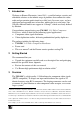
Introduction 1 Introduction Welcome to Kramer Electronics (since 1981): a world of unique, creative and affordable solutions to the infinite range of problems that confront the video, audio and presentation professional on a daily basis. In recent years, we have redesigned and upgraded most of our line, making the best even better! Our 350-plus different models now appear in 8 Groups1, which are clearly defined by function.
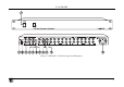
Your VM-100C To achieve the best performance: • Connect only good quality connection cables, thus avoiding interference, deterioration in signal quality due to poor matching, and elevated noise levels (often associated with low quality cables) • Avoid interference from neighboring electrical appliances that may adversely influence signal quality and position your Kramer VM-100C away from moisture, excessive sunlight and dust 4 Your VM-100C Figure 1, Table 1, and Table 2 define the VM-100C 1:10 Video Comp
Your VM-100C Figure 1: VM-100C 1:10 Video Component Distributor 3
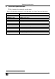
Your VM-100C Table 1: Front Panel VM-100C 1:10 Video Component Distributor Features # 1 Feature Function POWER Switch Illuminated switch supplying power to the unit Table 2: Rear Panel VM-100C 1:10 Video Component Distributor Features Feature Input Termination Button 2 3 4 Y RCA Connector R-Y RCA Connector B-Y RCA Connector LOOP # 1 Function Pushing in selects 75Ω; releasing selects Hi-Z1 For looping the inputs (if required) OUT INPUT 5 Y RCA Connector 6 R-Y RCA Connector Connects to the component
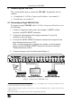
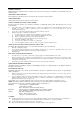
Connecting the VM-100C 5 Connecting the VM-100C This section defines how to connect the VM-100C. In particular, how to connect: • A single unit (1:10 Video Component Distributor), see section 5.1 • Several units, see section 5.2 5.1 Connecting a Single VM-100C Unit To connect a single VM-100C unit (1:10 Video Component Distributor), do the following1: 1. Connect a component video source (for example, an HDTV satellite receiver) to the RCA INPUT connectors. 2.
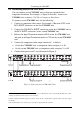
Connecting the VM-100C 5.2 Connecting Several VM-100C Units You can connect several VM-100C units to form an expanded video component distributor. For example, as Figure 4 illustrates, connect two VM-100C units to form a 1:20 Video Component Distributor. To connect several VM-100C units, do the following1: 1. Connect a component video source (for example, a Betacam VCR) to the RCA INPUT connectors on the first VM-100C unit. 2.
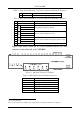
Technical Specifications 6 Technical Specifications Table 4 includes the technical specifications: 1 Table 4: Technical Specifications of the VM-100C 1:10 Video Component Distributor INPUTS: 1 set of component video (Y, Pb/Cb, Pr/Cr) on RCA connectors OUTPUTS: 10 sets of component video (Y, Pb/Cb, Pr/Cr) on RCA connectors 2.5Vpp 450MHz, Fully Loaded 0.03% 0.03 Deg <0.05% 76.8dB –51dB Level: –1dB to +6.4dB; Equalization: 0dB to +7.
LIMITED WARRANTY Kramer Electronics (hereafter Kramer) warrants this product free from defects in material and workmanship under the following terms. HOW LONG IS THE WARRANTY Labor and parts are warranted for three years from the date of the first customer purchase. WHO IS PROTECTED? Only the first purchase customer may enforce this warranty. WHAT IS COVERED AND WHAT IS NOT COVERED Except as below, this warranty covers all defects in material or workmanship in this product.
For the latest information on our products and a list of Kramer distributors, visit our Web site: www.kramerelectronics.com. Updates to this user manual may be found at http://www.kramerelectronics.com/manuals.html. We welcome your questions, comments and feedback. Kramer Electronics, Ltd. Web site: www.kramerelectronics.com E-mail: info@kramerel.