Standalone Digital Video Recorder Premium DVR 4, 8, 16 Channel Models User`s Manual MADE IN KOREA CKPM2108G13DKQ This document contains preliminary information and is subject to change without notice.
FCC Compliance Statement Notice to Users: This equipment has been tested and found to comply with the limits for a Class A digital device. Pursuant to Part 15 of the FCC Rules, these limits are designed to provide reasonable protection against harmful interference when the equipment is operated in a commercial environment.
Cautions This product has free voltages (100V ~ 240V). See installation instructions before connecting to the power supply. This product uses a Lithium battery. To avoid any risk of explosion, do not replace the battery on the main board by anything other than a Lithium battery. Dispose of used batteries according to the manufacturer’s instructions. This equipment and all communication wirings are intended for indoor use only.
12. Servicing Do not attempt to service this equipment yourself. Refer all servicing to qualified service personnel. 13. Damage Requiring Service Unplug this equipment from the wall outlet and refer servicing to qualified service personnel under the following conditions: ① When the power-supply cord or the plug has been damaged. ② If liquid is spilled or objects have fallen into the equipment. ③ If the equipment has been exposed to rain or water.
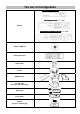
The List of Configuration S (4, 8 CH), A and E (4CH) Type : 4 / 8 / 16CH B and E (8, 16CH) Type : 4 / 8 / 16CH DVR Set C, D, F, G, H, I and J (8, 16CH) Type : 4 / 8 / 16CH Manual / CMS CD Remote Controller Quick Guide Screws HDD Brackets Rack Bracket (Except S, A, B and E Type) Data Cable Power Cable Adapter (Except G 8/16CH Type) 5
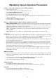
Mandatory Setup & Operation Precautions STEP 1. Date / Time Configuration (‘before’ HDD(s) installation) Plug a network cable, if any. Turn on the DVR and press ‘OK’ on no HDD(s) detection message. Go to SETUP>SYSTEM>General>Setup. Check on ‘NTP Setup’ box, and then select your ‘Time Zone’. Select DST (Daylight Saving Time) ‘On’ or ‘Off’ accordingly. When the DVR has no internet connection, adjust Date/Time manually.
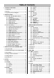
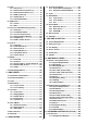
Table of Contents 4.3.5 Camera ..................................................53 4.3.6 Audio .....................................................54 4.3.7 Text-In ...................................................54 1. PRODUCT FEATURES ................................ 11 1.1 Unpacking ....................................................... 11 1.2 Service ............................................................ 11 4.4 RECORD ..........................................................54 4.4.
.1 Program Installation .....................................123 8.1.1 System Recommendations ...............123 8.1.2 Program Installation Method ............123 6.5 View ................................................................. 91 6.5.1 Server List ............................................ 92 6.5.2 Remote Device System Log ............... 92 6.5.3 Remote Device Event Log .................. 92 6.5.4 CMS System Log ................................. 93 6.5.5 Health Check.........................
13.3.1 Introduction ........................................180 13.3.2 Features ..............................................180 13.3.3 Technical Specification .....................181 13.3.4 Unpacking ...........................................181 13.3.5 Service ................................................181 13.3.6 System Dimension Diagram .............181 13.3.7 Connector Wiring ...............................181 13.3.7.2 RS-485 Connection ........................182 13.3.7.
13.8.7 Connector Wiring ...............................191 13.8.8 Cable ...................................................191 13.8.9 Display ................................................192 13.8.2 Features ............................................. 190 13.8.3 Technical Specification .................... 190 13.8.4 Unpacking .......................................... 190 13.8.5 Service ................................................ 190 13.8.6 System Dimension Diagram .............
1. Product Features 1.1 Unpacking This equipment is an electronic appliance, so it should be handled with special care. After unpacking, please check if all the following items are included. - DVR Main body - S Type : Power Supply Adapter (DC 12V, 3A) and Power Supply Cable - A, B and E (4CH) Type : Power Supply Adapter (DC 12V, 5A) and Power Supply Cable - C, D, E (8, 16CH), F, G (4CH), H, I and J Type : Power Supply Adapter (DC 12V, 6.
A Type – 4 / 8 / 16 channel Series DVR 12
B Type – 4 / 8 / 16 channel Series DVR 13
C Type – 4 / 8 / 16 channel Series DVR 14
D Type – 4 / 8 / 16 channel Series DVR 15
E Type – 4 channel Series HD-SDI DVR 16
E Type – 8 / 16 channel Series HD-SDI DVR 17
F Type – 4 / 8 / 16 channel Series HD-SDI DVR 18
G Type – 4 channel Series HD-SDI DVR 19
G Type – 8 / 16 channel Series HD-SDI DVR 20
H Type – 4 channel Series HD-SDI DVR 21
I Type – 4 + 4 / 4 + 12 channel Series Hybrid DVR 22
J Type – 8 / 16 channel Series True Hybrid DVR 23
2. Installation 2.1 Hard disk and DVD-RW Installation 2.1.1 SATA Port When installing HDDs, make sure to connect from SATA 1 Port. S and E (4CH) Type - Main board of this DVR has one SATA port: it is indicated as SATA 1. A Type - Main board of this DVR has two SATA port: it is indicated as SATA 1 and 2. B and E (8, 16CH) Type - Main board of this DVR has three SATA port: it is indicated as SATA 1, 2 and 3. - Please mount DVD-RW at the SATA 3 port.
2.1.2 Internal SATA Storage C, D, F, G, H, I and J Type DVR have 5 internal SATA Ports. 1-4 SATA Port: It is designed to mount HDD. Connect from SATA 1 port when installing HDDs. 5 SATA Port: Please mount a DVD-RW. Only one DVD-RW can be installed among the SATA Ports. 2.1.3 e-SATA External Storage (C, F, G, H, I and J Type) These series DVRs have one external SATA Port; the picture above shows external SATA 6 Port. 6 SATA Port: It is designed to mount up to 4HDDs per external SATA Port. 2.1.
2.2 Connector Wiring 2.2.1 Video-In/Loop Out Connections S, A, B, C and D Type Connect Analog camera to ‘VIDEO IN’. If a user wishes to link a camera input to another device, use ‘LOOP OUT’. (C and I Type). Assure the ‘VIDEO IN’ (top connector) and ‘LOOP OUT’ (bottom one) connections are connected properly, not opposite way. E, F, G and H Type Connect HD-SDI cameras to ‘HD-SDI IN’ from channel 1 to 16. I Type Connect HD-SDI cameras to ‘HD-SDI IN’ from channel 1 to 4.
2.2.4 HDMI connections Connect HDMI cable to HD out port of rear panel and HDMI port of HD output device. Please Click ( ) SETUP> DEVICE > DISPLAY > General and the following screen will display. Click the box below to select resolution. - A user can select the resolution among ‘1920x1080 (60Hz)’, ‘1920x1080 (50Hz)’, ‘1280x720 (60Hz)’, ‘1280x720 (50Hz)’ and ‘1024x768’. - If the resolution is changed then the DVR may restart automatically. - The default setting of DVR is ‘1920 x 1080 (60Hz)’.
2.2.8 Master Alarm (C, D, F, G, H, I and J Type) Alarm In sensor will be deactivated if Master Alarm is on. Connect Master Alarm In to ‘M’ connectors. 2.2.9 Alarm Connections [Relay (Dry Contact)] (Except S Type) Connect Alarm Output (buzzer, siren, etc.) to ‘NO and/or NC’ connectors, Power to ‘COM’ connector and Ground to ‘GND’ connector. 2.2.10 RS-485/422 Connections PTZ Camera and Keyboard controller connector. Please use TX+, TX-, RX+ and RX- terminals accordingly. 2.2.
2.2.16 Connections Guideline Video out Connector: If only the monitor is connected to VIDEO OUT connector, please set the impedance switch on the rear side of the monitor to 75 ohms to prevent abnormally bright or collapsed images. If wish to connect another device (e.g., a recorder) to the back of the monitor, please set the impedance switch on the rear side of the monitor to HIGH Z (High Impedance) and set the last device to 75 ohms.
3. Input Device and Screen Icons 3.1 Key and LEDs B and E (8, 16CH) Type KEYS ▲, ▼, ◄, ► PTZ KEY Operating mode • Control Pan/Tilt rotation of up/down/left/right in PTZ mode MENU • Enter the Main Menu (Setup mode) DISPLAY • Select 1/4/8/9/10/16 channel display.
C, D, F, G, H, I and J Type KEYS PTZ KEY Operating mode ▲, ▼, ◄, ► • Control Pan/Tilt rotation of up/down/left/right in PTZ mode 1 ~ 10 / 10+ • Camera select keys : (4/8/16 channel DVR) DISPLAY • Select 1/4/8/9/10/16 channel display. SEQUENCE • Channel sequence mode on/off (Main Monitor) ARCHIVE • Copy video data into the external storage device FREEZE • Screen freeze mode on/off AUDIO/ESC • Audio on/off on selected channel (Live View).
3.2 Camera Select Keys for 16 Channel DVR B and E (8, 16CH) Type Below shows how to select camera channel for 4 channel DVR - Select Camera No. 1~4: press key and use 1~4 key Below shows how to select camera channel for 8channel DVR - Select Camera No. 1~8 press key and use 1~8key Below shows how to select camera channel for 16hannel DVR - Select Camera No. 10~16: press 1~6 key C, D, F, G, H, I and J (8, 16CH) Type Below shows how to select camera channel for 16 channel DVR - Select Camera No.
3.3 Front Panel S (4, 8CH), A, E (4CH) Type 4 / 8 / 16 Channel DVR B and E (8, 16CH) Type 4 Channel DVR 8 Channel DVR 16 Channel DVR C, D, F, G, H, I and J (8, 16CH) Type 4 Channel DVR 8 Channel DVR 16 Channel DVR 3.4 Using a Remote Controller Usage of a remote controller is same as the front panel keys. Follow the procedure below when you use one remote controller for multi DVRs. ① Check System ID (e.g., between 1 and 255) of the DVR that wish to use.
3.5 Using a Mouse Mouse provides an easier access to adjustment. Refer to below for proper use. Left mouse button functions the same as Enter ( ) key on the front panel of DVR. Right mouse button displays the channel function key such as Audio, PTZ, PIP, Color and Position on selected channel. S, A, B, C and D Type Function Name of Key Audio Enable/Disable Audio Color Change Brightness / Contrast / Saturation of the selected channel.
3.6 Screen Icon Icon Description Icon Continuous recording schedule Continuous + Motion recording schedule Motion recording schedule Motion + Alarm recording schedule Alarm recording schedule Cont. + Motion + Alarm recording schedule Continuous + Alarm recording schedule No Record Continuous recording mode Motion recording mode Alarm recording mode Emergency recording mode Audio recording (When connected) PTZ registration Remote access indication/ No.
4. Setup 4.1 Login For security purpose, a user has to input the password to enter the setup menu. Please press from Display Menu Bar to enter the setup menu and the following screen will display. In order to use all functions and privileges, log in as ID: admin. Default Password is “1111”. After login successfully, following screen will display. Main menu consists of 4 sub menu.
4.2 SYSTEM 4.2.1 Status Entering Setup Menu following screen will display. System Status show information of the DVR like followings - DVR name - DVR ID - MAC Address - Firmware - Date - Language - IP Address - UPnP - Video Signal - HDD Usage - Camera / Audio Connection - HDD information - Record Start & End time NOTE Values cannot be changed at ‘Status’. Please see ‘General’ to change the value. 4.2.2 General Please Click ( ) SYSTEM>General and the following screen will display.
Setup DVR Name Name your DVR on your own. Please Click ( ) keyboard icon on DVR Name box and the following virtual keyboard will display. Please Click ( ) desired letters (characters) on the virtual keyboard to input. ① ② Use to erase one character every time. Use to erase the whole line. ③ Use to move the cursor (Also you can use a mouse to move the cursor between characters) Please choose ‘OK’ to confirm the input and choose ‘Cancel’ to cancel.
Setup Import: Copy a DVR configuration file stored in USB memory stick to DVR. Please plug in the memory stick and then Click ( ) - Please choose ‘OK’ to confirm and choose ‘Cancel’ to cancel. Export: Store the Menu setup of DVR to USB memory stick. Please plug in the memory stick and then Click ( ) Default: Click ( ) to restore all setup values to default settings - Please choose ‘OK’ to confirm and choose ‘Cancel’ to cancel. NOTE Import or Default process may restart the DVR.
Please Click ( ) Select box next to Check NTP Server in Interval to sync the time regularly by selected interval. NTP Server: Click ( ) or address in NTP Server box and the virtual keyboard will display. Input IP address of NTP server Check Interval: Set clock-update-interval from NTP Server. A user can adjust time every 1 to 24 hours. Please choose ‘OK’ to confirm the NTP setup, choose ‘Cancel’ to cancel. NOTE Check the box next to operate the NTP function properly.
Firmware Users may upgrade DVR when it is required. Please follow the Upgrade process below. ① Plug USB memory stick which has a proper firmware file. ② Click ( ) Then, software version stored in the USB will display on the left-hand side. ③ Click ( ) to start the upgrade. ④ Popup message box will display and ask to proceed. Click ’OK’ to proceed. ⑤ When the upgrade is completed, a message box will display. Please Click ‘OK’ button and DVR will auto-reboot.
Then, lists of User will show as follows. To Edit the User, Select a User from the list and Click ( ) To Delete the User, Select a User from the list and Click ( ) NOTE Only ‘Admin user’ can access Account menu. NOTE E-mail address is not mandatory to create New User but it is necessary to send email notification. NOTE A user may create up to 8 Groups and 8 Users per Group. Login Check Selectively enable password protection for important operations.
System Log shows various event logs by User ID(s) like below - System Start - System Reboot - Setup Default/Import/Export - Resolution Change - Video out Change - Time Adjust Before/After - NTP Sync Success/Fail - Firmware Upgrade Success/Failure - Log Delete/Export - Setup Enter/Exit - Playback Start/Exit - Archive Success/Failure/Cancel - Video Loss Occur - Network Connect/Disconnect - Setup Change from Remote - E-mail Send Success/Failure - HDD Add/Remove/Relocate - HDD Format Success/Failure - Data Cl
4.3 DEVICE 4.3.1 Display Please Click ( ) DEVICE>Display and the following screen will display. General Users are able to set its video output resolution between 1024 x 768 ~ 1920 x 1080. Video In / Out will help users to select its video input and output between NTSC, PAL and AUTO. The default value is ‘AUTO’. Once the setting is changed, it will ask to reboot for the new recognition of video out. Transparency option allows a user to adjust a level of transparency of menu display.
Position (OSD) Position (OSD) menu allows a user to adjust the position of Channel OSD on the monitor. Use it when some letters are dropped/invisible/blocked on the monitor. Adjust Horizontal to change margin between both ends of the monitor on horizontal side and OSD. Margin range is between 0 and 50, with a larger number representing greater margin. - Use ▲, ▼ to adjust position of OSD Adjust Vertical to change margin between both ends of the monitor on vertical side and OSD.
To adjust the location of the cameras for each sequence, Click ( ) each Drop-down list and able to select the channel. To adjust the rotation interval of cameras, Click ( ) each Drop-down list and select from 3, 5, 10, 15, 30 and 60 seconds. If Click ( ) at the top Drop-down list in X1 Seq, Users can adjust all items of interval at once. To activate Sequence mode during live monitoring, click Bar on the left margin of the main monitor.
4.3.2 Network Please Click ( ) DEVICES>Network and the following screen will show. LAN LAN Please Click ( ) Network Type. When you click the Drop-down list, users can select to Static (fixed IP) or DHCP (floating IP). In Static, a user must manually set the static IP address for use. - Set IP Address, Subnet Mask, Gateway DNS Server 1 & 2. Please ask your network administrator for more details. - To input address, please Click ( ) Numpad icon on the right-hand side of each box.
CAUTION IT IS NOT POSSIBLE TO CHANGE PORT NUMBER, WHEN A USER IS CONNECTED TO THE DVR VIA NETWORK. ONCE PORT NUMBERS ARE CHANGED, IT MUST BE ALSO CHANGED THE PORT NUMBERS ON REMOTE SOFTWARE SUCH AS CMS Pro, mViewer Pro, iCMS and xCMS. Dual Streaming To change Frame rate and qualities of dual streaming for Live monitoring, uncheck from the checkbox next to Default Value. - Frames : 1, 3, 5, 7, 15 frames for NTSC (1, 3, 5, 6, 12.
NOTE DDNS service port number 95 is NOT required to be port forwarded at all. CAUTION WHEN A USER’S CONNECTIONG DEVICES (PC, Mac, SMART PHONES, etc.) ARE UNDER THE SAME ROUTHER WITH A DVR, THE USER CANNOT USE THE DDNS NAME TO CONNECT. USE THE DVR’S PRIVATE IP ADDRESS FOR THIS CASE. 3rd Party DDNS - Check a checkbox of 3rd Party to use dyndns.org or no-ip.com Server. - As for DDNS Server, dyndns.org will be showing as default. To change server, Click ( ) Drop-down list of DDNS Server.
Alarm In The Alarm In menu will allow users to give title and to select the type of Alarm input. Click ( ) the keyboard icon on the right-hand side of each box on name column or name column and the virtual keyboard will display. Then, please register the title of Alarm input. When a check box is marked on Use, a corresponding Alarm starts operating. However, if a user does not check the check box, the operation stops. If Click ( ) ‘All’ of use box, all items are check/uncheck at once.
HDD Format This page shows information of HDDs installed in the DVR. When users install full storage device and DVD-RW including one e-SATA storage(C, F, G H, I and J Type), then following procedures will be listed as below: - 1. Internal SATA 1~4 Ports - 2. External SATA 1~4 Ports - 3. DVD-RW Under “Information”, it is possible to find the port number where each HDD is connected. - For Internal SATA, [P1], [P2], [P3] and [P4] each represents internal Port 1, Port 2, Port 3 and Port 4.
Check Beep: When Bad detects from HDDs, it will give the alarm sound. Check Message: When Bad detects from HDDs, the alarm message will pop up on the OSD. NOTE When “Attention or Warning” is detected by S.M.A.R.T, notification (Alarm out, Email, Beep and Message) will not activate. Overwrite Click ( ) Overwrite and the following screen will display. Overwrite Setting Click ( ) Overwrite box and users may activate the overwrite function.
4.3.5 Camera Please Click ( ) DEVICE>CAMERA and the following screen will display. Click ( ) the each Name box and the virtual keyboard will display. Then, register names of cameras. If a check box is checked on Use column, a video of the corresponding camera is recorded and displayed on the monitor. However, if a user does not check the checkbox, “UNUSE” text will be displayed on the channel. If Click ( ) ‘All’, all items are check/uncheck at once.
4.3.6 Audio Please Click ( ) DEVICES>Audio and the following screen will display. The Audio menu allows a user to choose whether to record Audio, if connected When a check box is marked on Record column, corresponding audio and video from Linked Camera will be recorded. However, if the check box is not marked, audio will not record. And If Click ( ) ‘All’, all items are check/uncheck at once.
-HD-SDI Type- (Maximum Recording Rate by Resolution) E and F Type 30/60hz (25/50hz) 960x480 (960x576) 1280 x 720 1920 x 1080 4 Channel DVR 30 (25) fps per Channel 30 (25) fps per Channel 30 (25) fps per Channel 8 Channel DVR 30 fps per Channel 30 fps per Channel 15 fps per Channel 16 Channel DVR 30 fps per Channel 30 fps per Channel 15 fps per Channel 30/60hz (25/50hz) 960x480 (960x576) 1280 x 720 1920 x 1080 4 / 8 / 16 Channel DVR 30 (25) fps per Channel 30 (25) fps per Channel 30 (2
Continuous Please Click ( ) Continuous and the following screen will display. The Continuous menu allows a user to set occasional recording rates and resolution. Each box on Title column shows camera title registered in DEVICES>Camera. A user cannot change camera titles here. Click ( ) each box on Resolution column to select recording resolution of a corresponding camera. A user may select one of 360x240(288), 720x240(288), 720x480(576), 960x480(576), 1280x720 and 1920x1080.
Alarm Please Click ( ) Alarm and the following screen will display. The Alarm menu allows a user to set Alarm based recording rates and resolution. Each box on Title column shows camera title registered in DEVICES>Camera. A user cannot change camera titles here. Click ( ) each box on Resolution column to select recording resolution of a corresponding camera. A user may select one of 360x240(288), 720x240(288), 720x480(576), 960x480(576), 1280x720 and 1920x1080.
Emergency Please Click ( ) Emergency and the following screen will display. The Emergency menu allows a user to set Emergency based recording rates and resolution, when ‘Emergency button pressed. Each box on Title column shows camera title registered in DEVICES>Camera. A user may not change camera titles here. Click ( ) each box on Resolution column to select recording resolution of a corresponding camera.
4.4.2 Schedule Please Click ( ) RECORD>Schedule and the following will display. Setting The Schedule table displays one week divided by hour and date. Each cell represents one hour. A user may choose appropriate recording conditions by hour. Holidays could be defined by a user separately. Click ( ) Drop-down list of Camera box to select Camera. Please set the recording mode as follows: ① Mark a check box to select record mode in record mode table.
② Click ( ) on date needed to be registered as holiday. ③ Click ( ) ADD button and Virtual keyboard will display to input description of holiday ④ Please choose ‘OK’ to confirm the input and the date will be copied to the Holidays table. ⑤ If wish to delete the registration of a certain holiday, please Click button next to the Holiday table. Since holidays may vary every year, we recommend user to update on a regular basis. 4.4.
4.5.1 ALARM IN Select Alarm out, Preset and Notification to use when Alarm In sensor goes off. Link Notification displays E-mail addresses registered in System>General>Account>User>Email Please follow the setup procedures below. ① Click ( ) Drop-down list of Alarm In box and select Alarm In. ② Select Alarm out to be worked when selected Alarm In is on. Please check a check box of use column on Alarm Out box. More than one alarm outputs can be set.
⑦ Click ( ) Drop-down list of Duration box to set the duration of recorded data for attached EXE ⑧ Select Local Actions -Beep: When selected Camera detects Motion, it will give the alarm sound -Popup: When selected Camera detects Motion, it will make the popup screen on the main monitor -Message: When selected Camera detects Motion, the Motion message will pop up on the OSD Repeat the above procedure for Cam 2~ Cam 16 Click ( ) Copy to All CH button to copy Notification & Local Actions to all channels
4.5.4 TEXT-IN Please Click ( ) RELAY>TEXT-IN and the following screen will display. Select cameras for Preset, Alarm Out and Notification to use when Text In comes to DVR. (PTZ Preset is frequently used for this case). Link Notification displays E-mail addresses registered in System>General>Account>User>Email Please follow the setup procedures below. ① Click ( ) Drop-down list of Text In box and select Text 1. ② Select alarm outputs to be worked when Text In 1 is on.
Link Notification displays E-mail addresses registered in System>General>Account>User>Email Please follow the setup procedures below. ⑨ Click ( ) Drop-down list of camera box and select Cam 1. ⑩ Select alarm outputs to be worked when video loss is occurred to cam 1. Please check a check box of use column on Alarm Out box. More than two alarm outputs can be set. If Click ( ) ‘All’ of use box, all items are checked/unchecked at once ⑪ Select cameras for preset when video loss is occurred to cam 1.
5. OPERATION INSTRUCTION 5.1 Viewing 5.1.1 First Image Power on DVR and the attached cameras (if any) will display. The screen will display date/time and icons below. Icon Description Icon Continuous recording schedule Continuous + Motion recording schedule Motion recording schedule Motion + Alarm recording schedule Alarm recording schedule Cont.
On the right bottom side of the screen, disk usage will show by %. On the left top side of each channel screen , , , , , , , , , , , , , , icon will show as its operation. At the normal state, HDD Overwrite mode is on and icon shows. When Overwrite mode is off at DEVICE>STORAGE>Overwrite, Click Emergency recording button, Click Audio button, will show. icon will show. icon will show. And Click Audio button again to reactivate the Audio.
5.1.5 Pan / Tilt / Zoom Control Press PTZ key to operate a PTZ camera connected to DVR. PTZ operations are only available in the full screen format. In Pan/Tilt mode, the icon is displayed on the bottom of the screen. Please refer the below for PTZ OSD menu.
Available 1 ~ 255 Preset numbers can be saved it depends on camera specification. Press Menu button to pop-up PTZ camera OSD setup screen and set up Tour and Pattern items. - Since these functions make use of a memory function of the camera itself, a user should set them in Camera OSD. - Once a user completes the setup, close the Camera OSD menu. - A user can conveniently use Tour and Pattern functions simply by Clicking Tour and Pattern buttons.
5.2 Playback Press display. key on the System Menu Bar, or Press Search button on the front of the DVR and the following Search menu will There are two ways to search video, i.e., by Calendar and by event. - Calendar Search: search by using calendar. - Event Search: search by event. There are three other functions in playback mode; - : This function allows a user to take screenshot and save to USB in jpeg format.
Following is the key usage found in playback mode. A user may also use the keypad provided on the screen.
Follow the procedure below to search video by calendar. ① Select Year and Month by using the arrow buttons in the calendar. - : Move to next ‘Year’ : Move to previous ‘Year’ - : Move to next ‘Month’ - : Move to previous ‘Month’ ② Click ( ) on a certain date wish to playback. The date will be displayed in Blue color. ③ Click ( ) on the time bar and Red line will move to the selected time and playback will begin instantly. NOTE Time period on the time indication bar can be adjusted by mouse scroll.
5.2.2 Digital Zoom in Playback Users are able to use Digital Zoon function in full screen playback. Drag a partition on to the screen, then the partition will enlarge as a full screen. Double Click the left button of mouse to exit the zoom-in screen. 5.2.3 One-touch Playback Press the PLAY/PAUSE key or Click the mouse wheel (central button) in the viewing mode. Then, a user will be able to view the recorded video right away without going through the search procedure.
5.4 Bookmark Bookmark allows a user to save certain time during both live monitoring and playback mode. And able to go back to the bookmarked time during playback. Press in both Live and Playback mode and the following popup window will display. In Live, it is only possible to add the current time to the list. Please enter Name for each of the Bookmark time. A user can check the list in playback. In Playback, it is possible to add, delete and play from the Bookmark List. Press time to the list.
NOTE To archive in jpeg format please use snapshot in Playback mode. NOTE Please do not change the settings by DVR or CMS, while archiving. NOTE Please enter all the necessary information before Click ‘OK’. NOTE If the total archiving file size exceeds 2GB then the new archived file will be produced every 2GB. From the second file it will have Date and time stamp of the starting time after the original file name given by the user.
Professional Central Monitoring Software CMS Pro Full-featured Enterprise Class Surveillance Solution User`s Manual This document contains preliminary information and is subject to change without notice.
6. CMS Pro 6.1 CMS Pro Features 6.1.1 Introduction The CMS Pro is a central surveillance system solution that monitors multiple sites with video, audio and event signals from DVRs over networks. The software supports different windows of live viewer, playback player, interactive map viewer, various search panes and event signal monitoring panes. 6.1.2 Features This program does not limit the number of units to register and monitor.
6.2 Installation 6.2.1 Software Installation Please follow the program installation procedures below. ① If an old version of CMS Pro program was installed, it is recommended to completely uninstall or delete the old version. ② Insert the provided CD in a PC. ③ Run the CMS Pro Setup.exe file. ④ When the following screen appears, click “Next.” ⑤ When the following screen appears, select folder and click “Next.
⑦ When the following screen appears, click “Install.” ⑧ When the following screen appears, click “Finish” to complete the installation. NOTE If the PC has a previously installed CMS Pro, the installer may ask whether to overwrite the existing DB or not. The DB contains setting values on the program. If desired to maintain the existing values, click ‘No’ button. 6.2.2 Login 6.2.2.1 Login Process Open the CMS Pro.
NOTE Users may change the password in [Setup] – [Change Password] menu. For the detailed information, please refer to the ‘Chapter 6.4.7 Change Password’ page. The CMS Pro saves settings and layouts on the program of the current user when the program is closed. 6.3 Menu Below shows the brief explanation of each part on the screen.
6.4 Setup 6.4.1 Local Setup - Device Please make sure the network setting of DVR has been done properly prior to the remote connection setting. 6.4.1.1 Remote Site Connection Setup Click Setup – Local Setup – Device to enter the setup and a dialog will pop up as below picture. 6.4.1.2 New Device Register Device Select “Device Connection List” on left-hand side and click [New] to register new devices. Describe the connection information as below.
Camera Choose a camera name between DVR and CMS setting or both. - Device Camera Name: Display camera name of DVR. - CMS Camera Name: Display Camera name of CMS. - Both (Device-CMS) Camera Name: Display both as [DVR name]-[CMS name]. If users mark the “Display to Server List”, camera name is displayed in the server list. Type the name of each camera in “Camera Name” item. Users will be able to type not only in English but also in their own languages.
6.4.1.4 Remove Registered Site Select a site to delete on local setup window and click “Remove” The site will be removed on the local setup window. 6.4.2 Device Group Setup It is possible to make a group of multi-devices for user’s convenience. - Users are able to combine multiple devices as one group of connection for easy control. - Users are able to extract the cameras from registered DVRs to make own group of display. 6.4.2.
6.4.2.3 Remove Group Setting Select a group to delete on Group Setting window then click “remove” The group will be removed on the local setup window. 6.4.3 Local Setup - Environment This enables users to adjust the default setting of CMS Pro software for user’s convenience. 6.4.3.1 System Users are able to check the current version of the software. Users are able to select the language among English, Korean, Japanese, Russian, Turkish, Finnish, German and French. 6.4.3.
NOTE If users check “Show covert video” box, this setting will be applied to playback as well. NOTE All changes made above will be applied after program restarts. Date / Time format: Users can adjust and set the mode of date / time display in accordance with the location. - Date/Time: show current time. - Date Format: select the date format among YYYY-MM-DD/MM-DD-YYYY/DD-MM-YYYY. - Time Format: select the time format between 24Hours/ 12 Hours AM/PM.
Instant Recording Users can customize the storage path of the instant recording file by selecting HDD installed in PC. - Select Drive: Select PC’s HDD where instant recording file should be saved from the drop down menu and click “Add”. It will show Drive type, Free Space and Total Space of selected HDD. - Storage List: Added HDDs can be prioritized or deleted. Use Up and Down arrow to prioritize and “Delete” to remove HDD from the list.
Setup Import: Copy the Menu setup stored in USB memory stick (or PC HDD) into DVR. Please plug in the memory stick and then click ( ) Import. Setup Export: Store the Menu setup of DVR in USB memory stick (or PC HDD). Please plug in the memory stick and then click ( ) Export. Apply: Click the “Apply” button to apply the settings. 6.4.3.5 Instant Playback Instant Playback: Users are able to see the recorded data easily by using instant playback function.
6.4.4.1 Add User Account Click “New” button and the following will display. Type: Select one of the two types of user account, Manager and User from the drop-down menu. - While Manager Account allows all of the authorization to be controlled, User Account is permitted to set only Search, PTZ control, and E-map functions. Create a User name and Password and then type Description of the account. Mark the authorization check boxes ( ) to allow.
6.4.5.1 Registering a New E-map Click “New” Tab to set up the E-Map. In order to load an image of the map, click “Load Map Image” that users would like to use as an E-Map. Users should select the image format between BMP and JPG. Place the icon of cameras, audios and alarms on the map. Each icon’s detail is as below. - Box Camera: Generally indicates as Outdoor camera. - Dome Camera: Generally indicates as Indoor camera. - Alarm/Sensor: The icon is blinking on when the alarm in is activated.
Select Size: Size of the icon varies from 24*24, 32*32 to 48*48. Edit Name: Type the name of the icon and click the “Apply” to change the name. Reposition: The icons which are set up on the map can be repositioned into the right place even if the map size is changed (enlarged/reduced). Delete All Components: By clicking this button, users can delete all the components in the map at once. Font: Change the font of the text of the icon. - Click “font”, then submenu will display.
Click “Save” to save and exit. 6.4.6 Remote Device Setup Select a device to enter device’s configuration and Click “OK” then the web browser will pop up as below. Enter ID and Password to open Remote Device Setup page and following page will display. Web server port (default, 80) should be port forwarded to use remote device configurations. NOTE Remote Device Setup menu shows the same menu interface as the DVR’s local menu. Please refer to Chapter 4. Setup for detailed information.
6.4.6.1 System Refer to 4.2 System for more detail. 6.4.6.2 Device Refer to 4.3 Device for more detail. 6.4.6.3 Record Refer to 4.4 Record for more detail. 6.4.6.4 Relay Refer to 4.5 Relay for more detail. NOTE Some settings cannot be modified remotely. NOTE The changed password cannot be restored. Please keep and remember not to lose! 6.4.7 Change Password Users are able to change the using password of the ID, when they open the software. This is not related to any DVR’s login password.
6.5.1 Server List When the device is registered, then it is displayed on the Server List. If uncheck “Visible” in the server list menu, then the list will not be shown. Check “Left” or “Right” to move the list to left or right side of the screen. 6.5.2 Remote Device System Log User can check the system log of the device in this menu. Type, Date/Time/Description can be checked. The contents in the parenthesis show the name of the device.
NOTE The Remote Device Event Log is on when the “pause” is shown while the log is stopped when the “resume” is shown in the menu. Double click the detected “Alarm In” or “Motion” event in the remote device event log to check the video of the event. Click the “Refresh” button to refresh the data. Click the right mouse button on the registered device to on/off Event Log in the Server List. A user selects “Event Log Off”; all event logs will be unchecked on Remote Device Event Log panel. 6.5.
Check “Visible” in the Health Check to see the menu or uncheck “Visible” in order not to see the menu. Left mouse click on the device in the server list to see the information of health check. HDD Status - HDD is not connected and cannot be added. - HDD is connected. - HDD is not connected currently but can be added. - An error occurred in HDD. Camera Status - Camera is in covert mode. - Camera is connected. - Camera is not connected currently but can be added.
6.5.6 Show All Windows This function will make visible all the invisible window panes. 6.6 Application 6.6.1 Search There are five different types of search menu; Timebar, Event, POS/ATM, Thumbnail and Smart Search The detailed information and directions is described in chapter 6.8. 6.6.2 Exit If users wish to exit the program, then click the “Exit” in the Application menu.
6.7 Live (Live Video Monitoring System) 6.7.1 Overview This program is to display live video from multiple channels in customized screen format. The program is based on user friendly interface. Users may configure the entire program and open or close the panes and screens in the program. The information of the device can be checked and monitored in real time. The overall information of recording/live view can be checked.
6.7.2.3 Instant Playback Instant playback is available in both Live1 and Live2 pane, but screen capture is available in either live1 or live2. After right mouse click, move the mouse cursor to “Instant Playback”. Then, play and setup menu will display. - Play: The recorded video of the pre-setup time will be displayed in the playback viewer. - Setup: The time of instant playback can be setup in this menu, from 1minute to 3hours. (1Min, 3Min, 5Min, 10Min, 15Min, 30Min, 1Hour, 3Hour.
Zoom in / out function Zoom In Zoom Out Zoom Area: The Screen will revert to x4 digital zoom screen. Zoom Area NOTE Digital Zoom function can be only used when the display is on 1Ch mode. The digital zoom function is able to zooming approximately x32. 6.7.2.5 PTZ Control After right mouse click on the channel that PTZ camera is connected, select “PTZ control”. Users can designate the certain position and set the name by using “Preset” function. Up to 255 presets can be designated.
Zoom - Zoom in - Zoom out Focus - Near Focus - Far Focus Iris - Iris Open - Iris Close Preset - Set Preset - Go to Preset - Drop down menu: Select a preset number which is set in the camera. - Preset Name: Save the selected preset name. 6.7.2.6 Screen Capture & Print After right mouse click, select “Capture & Print Screen” The brightness, contrast and saturation can be adjusted to store and can be printed directly.
Click “Hide Captured Image” to hide the captured images. 6.7.2.7 Audio On/Off Right click and select Audio On/Off to turn on/off audio from the channel. Audio On/Off function is applied to only one channel out of all connected channels. - Once audio is on “ ” will be changed to show connected audio channel. “ ” 6.7.2.8 MIC On/Off Click right mouse button to turn on/off microphone of PC.
If a user wants to have password for the archiving file, please click ‘Use Password’ and type the password that users want to use. If users click ‘OK’, it will start recording of that specific channel. When users want to view the archived file, please choose “Open Folder” It will open the saved directory of the file. When users double click the created file, password window will pop –up.
6.7.2.10 Display Option Users can set up the display of camera name and time in “Display Option”. After right mouse click, check the “Show Camera Name” to display the camera name or uncheck the menu to hide it. After right mouse click, check the “Show Time” to display time or uncheck the menu to hide it. 6.7.3 Screen Layout Control Every menu pane can be relocated by drag and drop. 6.7.
6.7.6 Audio Volume Control Users can control the audio volume using the bar controller at the bottom of the screen. 6.8 Search 6.8.1 Overview 5 ways of Search are available. (Time Bar Search, Event Search, POS/ATM (keyword) Search, Thumbnail Search, and Smart Search). NOTE Search window cannot be closed during playback, also cannot be changed window size. Please close the window after stop. Playback more than 2 channels at the same time is available only in time bar search. 6.8.
Users can change the speed of rewind and fast forward from x1 to Extreme. The actual speed may be limited by DVR’s network uploading bandwidth. Users can use Right click to access Audio On/Off, Digital Zoom and Capture and Print Screen. - Audio On/Off: A user can enable audio function. If Audio is connected Audio Status will change. - Enter Digital Zoom: A user can use Digital zoom. Please refer 6.7.2.4 Digital Zoom. - Capture and Print Screen: A user can capture image. Please refer 6.7.2.
Select a start time, end time, file name, the location of the file, password and the cameras to store. Click “Start EXE Backup” to start archiving. NOTE Archiving function can be initiated only in time bar search. 6.8.3 Event Search Click the “connect” after right mouse clicking on the device and select the “Event Search”. Check the event type which users wish to search among “Emergency”,” Alarm” and “Motion”.
Display Position – Users are able to select the text display option of the playback. - Text Window: Only text will be displayed in the top right side of the search window during the playback. - Overlay: The text will be overlaid on the playback video. - Both: The text will be overlaid on the video and the text window as well. - Hide All: The text will not be displayed in both video and the text window.
Users are able to select the one from the 3 types of sensitivity level; Super, High and Standard. 6.9 E-Map 6.9.1 Overview The ‘Map Viewer’ program is to display event signals over map images so that users may acknowledge event status more easily. Users may recognize event occurrence with visual notifications on icons over the map image and audible notifications on speaker system of a PC. By clicking on the camera icons on the map, users may launch ‘Instant Viewer’ window.
Full screen mode is available by clicking right mouse button and select “Full screen”. Click audio icon to listen to the audio of the channel, if audio input connected. Click the alarm out icon to release a manual relay signal to the site such as siren or buzzer 6.9.4 Alarm In/Out Control The Alarm In icon on the map is blinking when the Alarm In equipment like sensor or detector is activated. Click the alarm out icon to release a manual relay signal to the site such as siren or buzzer. 6.9.
iCMS iCMS User`s Manual This document contains preliminary information and is subject to change without notice.
7. iCMS VIEWER 7.1 System Recommendations Recommended Core 2 Duo 2.26GHz or higher CPU 2GB or higher Main Memory 512MB or higher Video Memory Display Resolution 1024ⅹ768 (with 32bit color) or higher HDD Storage Space 30GB or higher Network Operating System 100~1000 Mbps Fast Ethernet Mac OS 10.6.0 or higher NOTE It is recommended to connect Max. 16 HD-SDI (Full HD) cameras with iCMS.
In the virtual driver, users will find iCMS icon. Please move the iCMS icon to ‘Application’ folder (‘Application’ folder is located in the ‘Go’ Menu below). 7.3 Login After installation of the software, iCMS icon appears in ‘Application’ folder. Please double Click on the icon to execute the program. Select User Name by Clicking upside down arrow and enter corresponding Password to login. 7.4 Watch Mode 7.4.1 Log-in Screen Please Click ‘Device manager’ and the following screen will display.
7.4.2 Local Setting Please Click ‘Setup’ button on the top of the Toolbar and the following screen will display. There are three types of setup such as Device Manager, Display Setup and Password Change. 7.4.2.1 Display Manager Please Click ‘Device manager’ and the following screen will display. Users will see the existing DVRs on the list, if there is any added DVR previously. Please Click ‘Add’ to add new device.
If users want to scan the devices instead of typing the information manually, please Click ‘Scan device’. It will automatically detect DVR units currently connected to local networks. Click “Scan Device”, then following ‘Dialog’ will pop up. Including IP address, the information of connected DVRs in the network will be listed. Select the one and Click ‘OK’. Then, the following window will pop up.
Date / Time format: Users can adjust and set the mode of date / time display in accordance with the location. - Date Format: select the date format among YYYY-MM-DD/MM-DD-YYYY/DD-MM-YYYY. - Time Format: select the time format between 24Hours/ 12 Hours AM/PM. Display Font: Users can change the font of the name and display time of each channel. - Font Type: select the type of font between Arial / Courier. - Font Size: select the size of the font from 10 to 20 and the default is 15.
7.5 Live View 7.5.1 Connection Please choose one of the registered sites in Server list on the right hand side of the ‘Live Display’ screen and the right Click on the mouse button will pop up the menu with ‘Connect’. Click ‘Connect’ to connect the DVR. To have multiple channels, please choose the channel from the bar below the ‘Live Display’ screen (1, 4, 9, 16, 25, 36, 64 and Full). 7.5.2 Display Mode Full Screen Mode: Select a channel and Click on number “1” button.
NOTE The selected channel is outlined in blue 7.5.3 Health Check Please choose one of the registered sites in Server list and the right Click on the mouse button will pop up the menu with ‘Health Check’. Please choose ‘Health check’ function when users want to check the status of the DVRs. Now users can choose either Health Check or Monitoring to see the status of the DVR at the bottom of the right corner.
- Zoom In/Out, Focus Near/Far, Iris Close/Open Zoom Out/ In Focus Near / Far Iris Close / Open - Preset Control button Please choose the number from the drop down list from 1 to 256. After selecting the number, please type the description on the empty space below the drop down list and Click “Save”. If users think that the certain spot is important or need to have precautions, then they can set up the spot as ‘Preset’. When the preset is setup up, Click ‘Go Preset’ to move to preset spot.
Please choose one of the devices to playback from the Server List and right Click on the mouse to have popup menu with Connect. Select Date - In calendar, dates with recorded data are marked in red. Select the date among the dates marked in red. Select Time - Please select the time that users want to playback by Clicking ▲, ▼ buttons on the right-hand side to adjust the time or drag the Time Select Bar with mouse.
Please Click ‘Connect’ to start the event search Event search has Event Type, Select Camera and Date/Time setting. ① Event Type: it has Emergency, Alarm and Motion. Please choose one event that users want to use. ② Select Camera: Please select the camera that users want to view from Cam1 to Cam 16 for the event (Only 1 camera can be selected). ③ Date/Time setting: Please select the begin and end time by Clicking the up/down arrows and Click “Search” 7.6.
The following screen shows the result of the POS/ATM search. Double Click on the event to playback of the data. 7.
7.8 Uninstall Please go into the ‘Application’ folder and right Click on the iCMS icon.
xCMS xCMS User`s Manual This document contains preliminary information and is subject to change without notice.
8. xCMS VIEWER 8.1 Program Installation 8.1.1 System Recommendations Recommended Core 2 Duo 2.26GHz or higher CPU 2GB or higher Main Memory Display Resolution 1024ⅹ768 (with 32bit color) or higher HDD Storage Space 30GB or higher Network 100~1000 Mbps Fast Ethernet Fedora Operating System NOTE It is recommended to connect Max. 16 HD-SDI (Full HD) cameras with xCMS. WARNING DUE TO A LIMITATION OF A PC CONNECTING MORE THAN 16 HD-SDI (FULL HD) CAMERAS MAY RESULT IN MALFUNCTIONING OF THE SOFTWARE.
Please check the box right next to the “Allow executing file as program” and if users want to give access to other groups, please change the access level to Read and write. Right Click on the ‘xCMS’ and select ‘Open’ 8.2 Login Please right-Click on the icon and select open to execute the program. Select User Name by Clicking upside down arrow and enter corresponding Password to login. 8.3 Watch Mode 8.3.1 Login Screen After users log into the ‘xCMS’, the following screen will display.
8.3.2 Local Setting Please Click ‘Setup’ button on the top of the Toolbar and the following screen will display. There are three types of setup menu such as Device Manager, Display Setup and Password Change. 8.3.2.1 Device Manager Please Click ‘Device manager’ and the following screen will display. Users will see the existing DVRs on the list, if there is any added DVR previously. Please Click ‘Add’ to add new device.
Device Info - Device Name: input the DVR site name which will be displayed on the Server list. Please note that this name has nothing to do with the ID registered in DVR. Users may create a name that is fairly easy to distinguish. - Description: type brief description of the site. - IP Address: input IP address or Domain Name of DVR (check with SETUP>DEVICES>Network in DVR). - Command Port: input Administrator’s number among port numbers set in DVR (check with SETUP>DEVICES>Network in DVR).
Users can adjust and set the peripheral values of the display window. - Default Division: Users can select the number of division of display channels when the program initially displays the screen. (1, 4, 9, 16, 25, 36 or 64). - Users can choose either English or Korean in language setup. NOTE This option will be applied after program restarts. Date / Time format: Users can adjust and set the mode of date / time display in accordance with the location.
Click ‘Connect’ to connect the DVR to the ‘xCMS’. To have multiple channels, please choose the channel from the bar below the ‘Live Display’ screen (1, 4, 9, 16, 25, 36, 64 and Full). Full Screen Mode: Select a channel and Click on number “1” button. Then, the corresponding channel will display in Full Screen. Quad Screen Mode: Click on No.4 button and a quad screen will display. The quad screen is in combination of 1~4, 5~8, 9~12 and 13~16. If users select Channel No.
8.3.3.2 Health Check Please choose one of the registered sites in Server list on the right hand side of the ‘Live Display’ and then right Click on the mouse button will pop up the menu with ‘Health Check’. Please choose ‘Health check’ function when users want to check the status of the DVRs. Now users can choose either Health Check or Monitoring to see the status of the DVR at the bottom of the right corner.
Please choose the number from the drop down list from 1 to 256. After selecting the number, please type the description on the empty space below the drop down list and Click “Save”. If users think that the certain spot is important or need to have precautions, then they can set up the spot as ‘Preset’. When the preset is setup up, Click ‘Go Preset’ to move to preset spot. - PTZ control menu can be hidden by Clicking PTZ ICON below the PTZ menu. 8.3.3.
② ③ ① ⑤ ④ ⑥ 1 Fast Forward/Backward & Playback (Click the button to increase the speed by x1, x2, x4, x8, x16, x32, x64 and Extreme) 2 Sequence Mode 3 Display Mode( Click the button to divide the screen by 1, 4, 9, 16 and Full 4 Time Bar (24 Hour) 5 Data Bar (Recorded data) 6 Time Select Bar When Date/Time search is completed, please Click ‘Play ’ button to begin playback. 8.4.2 Event Search The Event search allows users to search event recorded data of DVR.
8.4.3 POS/ATM POS/ATM button allows users to search for the POS/ATM text data by keyword. Please Click ‘POS/ATM’ button right next to the ‘EVENT’ and users will see the following screen. Please choose one of the devices among the ‘Server List’ and right Click on the mouse to have popup menu. Please Click ‘Connect’ to start the event search Event search has Event Type, Select Camera and Date/Time setting.
The following screen shows the result of the POS/ATM search Double Click on the event that users want to display. 8.5 Disconnection When disconnect, please right Click on the connected site and choose ‘Disconnect’ Once users Click ‘Disconnect’, following screen will display with the message of ‘Disconnected’.
8.6 Uninstall Please go into the ‘Home’ folder and right Click on the xCMS icon. Please choose ‘Move to Trash’ to uninstall the xCMS program.
CMS Web Client Pro CMS Web Client Pro User`s Manual This document contains preliminary information and is subject to change without notice.
9. CMS WEB CLIENT Pro 9.1 System Requirements Web Client Pro may not run properly if the PC does not meet minimum requirements. Other programs should not run on the same PC where this is running. Otherwise, Web Client Pro software may not perform as designed.
9.3 Live Display After Login, following screen will display. ① ② ④ ③ The screen contains following features: ① Display current live video ② Setting display mode - Search: Opening search mode in new window. - PTZ: Open PTZ control panel. - Capture: Capturing the image of selected channel. ③ Audio controller - Able to control the volume. ④ Select display split mode. A user can choose 1, 4, 6, 8, 9, 13, 16 and Full screen. ⑤ OSD Font color - Able to change the color of the OSD font.
9.4 Search Screen Click then following screen will display on a new window. ① ② ③ ④ ⑦ ⑧ ⑥ ⑤ The screen contains following features: ① Searched playback video displays. ② Setting Date/Time to search. - Click a date in calendar, and then recorded data will be showed up in Time bar. - Start Time: Setting starts time. - Camera: Choosing camera number from 1~16 individually or all channels. ③ Play functions for playback.
9.5 PTZ Control Click then following screen will display on a new window. ① ② ③ ④ ⑤ ⑥ The screen contains following features: ① Pan/Tilt Direction button. ② Zoom In / Zoom Out control button. ③ Focus Near / Focus Far control button. ④ Iris control button ⑤ Preset control button ⑥ Camera select button. NOTE Must complete the control setting on its DVR and Cameras first.
9.6 Capture Click then following screen will display on a new window. ① ③ ④ ② ⑤ ⑥ The screen contains following features: ① Captured Image is displayed. ② Color Control ③ Save as Image ④ Original Image ⑤ Preview Print - A user can change Brightness, Contrast and Saturation of the captured image. - A user can save the edited image in new name. - A user can undo all modification made to the image. - Able to see print preview.
CMS Mobile Viewer CMS Mobile Viewer User`s Manual This document contains preliminary information and is subject to change without notice.
10. CMS MOBILE VIEWER 10.1iPhone / iPad (mViewer Pro) 10.1.1 System Requirements There are no other requirements to run this program because it is specialized to perform on iOSs interface. 10.1.2 Installation Turn on the iPhone or iPad then connect to App Store. Move to search menu and type “mviewer” then tap “ Select “ ” program which is offered by dvrdomain for free. When a user tap a “ Tap “ ”. ” button, it will be turned to “ ” ” to start installation.
If a user does not have the account, then Tap “ ” and it is registered by free. When a user registers the account, the program will be automatically installed. 10.1.3 Site Registration Tap “ ” icon on iPhone or iPad then below will show. Tap “ ” then below will show.
Tap “ ” and enter site information which are same as CMS Pro site registration. Enter Site Name, IP or DDNS address. Enter Admin/Stream port value. (Default, 5920/5921) Enter ID/Password. (Default, admin/1111) Tap “ ” to save the setting. To edit the saved site, tap “ ” next to site Name, then change the value, and tap “ To delete the saved site, slide the finger from right to left across Device Name. Then tap” 10.1.
10.1.5 Live View (Portrait View) To select other channels, - Slide finger from Right to Left to ascend. (1 → 2 → 3 …… 14 → 15 → 16) - Slide finger from Left to Right to descend. (16 → 15 → 14 …… 3 → 2 → 1) Tap “ Tap “ ” to take Snapshot. ” to enable Frame skip or Tap “ Tap “ ” to disable Frame skip. ” to choose split mode between 1, 4, 9 and 16. - In Multi-channel display mode, a user can double tap on certain channel to change to 1CH display mode. Tap “ ” to enable PTZ function.
10.1.6 Live View (Landscape View) To select other channels, - Slide finger from Right to Left to ascend. (1 → 2 → 3 …… 14 → 15 → 16) - Slide finger from Left to Right to descend. (16 → 15 → 14 …… 3 → 2 → 1) Tap “ ” to go back to main menu. Tap “ ” to choose split mode between 1, 4, 9 and 16. - In Multi-channel display mode, user can double tap on certain channel to change to 1CH display mode. Tap “ Tap “ ” to enable PTZ function. Please refer to 10.1.7 PTZ Control for more detail.
Touch “ ” to zoom out. Touch “ ” to zoom in. If users already set up the presets on DVR, users may use them by touching “ ”. 10.1.8 Search Users are able to search the recorded data with iPhone or iPad Tap “ ” on Main menu or “ ” on Live monitoring to use search function. Choose date that wish to search from Calendar Choose time to search by sliding the Hour and Minute bar. Tap “ ” to execute search. To select other channels, - Slide finger from Right to Left to ascend.
Tap “ ” or “ ” to disable Frame skip. Tap “ ” or “ ” to enable audio. (1CH display ONLY) Tap “ ” or “ ”to disable audio. (1CH display ONLY) To use Zoom feature, simply pinch and drag in 1CH display. (1CH display ONLY) NOTE Audio, Zoom and PTZ are available only in full screen mode. (1channel only) NOTE If a user enable frame skip, used memories will be stable and It’s possible to use it on live mode and playback mode. 10.1.
10.1.10 Setting Tap “ ” to check the information of the application. A user can read the manual. 10.1.11 Uninstallation Tap the “ ” icon and hold for a while until the program icon shows “x” mark on the top-left side. Tap “X” mark then Delete popup will show Tap “ ” button to successfully uninstall the program.
10.2Android Phone (mViewer Pro) 10.2.1 System Requirements This program is designed and applied only for Android OS (version 2.3 or higher) based mobile device. Display: Min. 3.7 inch screen NOTE mViewer Pro might not work even though Android OS version is high enough. It is due to the hardware specification of Android device. 10.2.2 Installation Turn on the mobile device then connect to Play Store.
10.2.3 Site Registration Tap “ ” icon on application menu then below will show. Tap “ ” on the main menu and tap “ ” on top right corner. Enter Device Name, IP/Host address. Enter Cmd/Stream port value. (Default, 5920/5921) Enter User ID/Password. (Default, admin/1111) Tap “ ” to save the setting. To edit or delete the saved site, press the Device Name for 2 sec from Live Device List and popup menu will display.
10.2.4 Connection Tap on Device Name to connect the DVR to mobile device. 10.2.5 Live View (Portrait View) To select other channels, - Slide finger from Right to Left to ascend. (1 → 2 → 3 …… 14 → 15 → 16) - Slide finger from Left to Right to descend. (16 → 15 → 14 …… 3 → 2 → 1) Tap “ Tap “ ” to enable Landscape view when the device is tilted ” to enable Frame skip or Tap “ ” to disable Frame skip. Tap “ ” to enable PTZ function. Please refer to 10.2.7 PTZ Control for more detail.
Tap on “ ” or “ ”to choose split mode between 1, 4, 9 and 16. - In Multi-channel display mode, a user can double tap on certain channel to change to 1CH display mode. Tap “ ” to take Snapshot. - Enter file name and press “ Tap “ ” to save the image. ” to remove Camera Name and Date/Time from OSD. NOTE Audio, Zoom and PTZ are available only in full screen mode.
Tap “ ” to enable PTZ function. Please refer to 10.2.7 PTZ Control for more detail. Tap “ ” to enable audio. Tap “ ” to remove Camera Name and Date/Time from OSD. Tap “ ” to take Snapshot. - Enter file name and press “ ” to save the image. NOTE Audio is available only in full screen mode. (1channel only) 10.2.7 PTZ control Users are able to control PTZ with mobile device by touching the screen. Tap “ ” or “ ” to execute PTZ function. Tap Arrow for Pan and Tilt movement.
10.2.9 Search Users are able to search the recorded data with mobile device. Tap “PLAYBACK” on main menu or “ ” on Live monitoring to use search function. Choose date and time that wish to search from Calendar Tap “ ” to execute search. To select other channels, - Slide finger from Right to Left to ascend. (1 → 2 → 3 …… 14 → 15 → 16) - Slide finger from Left to Right to descend. (16 → 15 → 14 …… 3 → 2 → 1) Tap “ ” to enable Frame skip or Tap “ Tap “ ” or “ ” to disable Frame skip.
Tap “ ” or “ ” to take Snapshot. - Enter file name and press “ Tap “ ” or “ ” to save the image. ” to remove Camera Name and Date/Time from OSD. NOTE Audio and Alarm Out are available only in full screen mode.(1channel only) NOTE If a user enable frame skip, used memories will be stable and It’s possible to use it on live mode and playback mode. 10.2.10 Snapshot Gallery Users are able to watch snapshot with the mobile device. Tap “ ” on main menu to enter the gallery.
- Tap “ - Tap “ ” to enable Password Lock when launching the mViewer pro. ” to change the password. 10.2.12 Uninstallation Move to Setup > Application > Manage Applications then select “ Tap “ ” icon then it will ask to delete the program. Tap “ ” button to successfully uninstall the program. 157 ”.
Keyboard Controller Keyboard Controller CP1300 User`s Manual This document contains preliminary information and is subject to change without notice.
11. KEYBOARD CONTROLLER (CP1300) 11.1 Connection A user may connect cameras and Keyboard to a DVR. Please see below for connection examples. RS485 ports are used for connections. 11.1.1 Configuration Diagram Example Please make sure to connect “Tx to Rx“ or “Rx to Tx” with same polarity. (+ to +) and (- to -). 11.1.2 USB Connection In order to use Touch Pad on CP1300, a user should connect CP1300 and DVR with provided USB cable. DVR will automatically recognize the Touch Pad. 11.
11.
System Log Key N/A N/A Emergency recording Key N/A N/A Search Key N/A Activate Tour Key Archive Key N/A Activate Pattern Key Spot control Key N/A Hold Key Pause on Live Key N/A N/A DVR Menu Key N/A N/A REW Key N/A N/A Backward Key N/A N/A Play/Pause Key N/A N/A Forward Key N/A N/A FF Key NA N/A PTZ Mode Key N/A Camera Menu Key N/A Activate Preset Key Open Iris Key N/A Set Preset Key Close Iris Key N/A Focus control Key Focus control Key N/A Zoom control Key
11.4 Setup 11.4.1 DVR Control Mode Press + in DVR Mode to enter Main Setup and enter password. (Default password is 0000) Keyboard Detail Option VER Firmware version - DATE Date setting YY/MM/DD TITLE SET Camera title - CONTROL ID ID No. Change - DVR SPD Set Baud rate 2.4Kbps~57.
11.5 Operation 11.5.1 DVR/SPD Mode Conversion Press “System ID” + “ ” to enter DVR control Mode. Press “Speed Dome Camera ID” + “ ” to enter PTZ camera control Mode. Example If a user wishes to connect to SYSTEM ID 3 DVR then press Num Pad “ “+ “ If a user wishes to connect to Speed Dome camera ID 3 then press Num Pad “ ”. “+“ ”. 11.5.2 DVR Control Mode 11.5.2.
- , - , , , : Playback control in DVR Search Mode. : View a channel in full screen (by selecting a number with ENTER button). NOTE For detailed information on PTZ Mode, please refer to 4.3.5 Camera. 11.5.2.3 PTZ Mode In order to enter PTZ mode, press “Camera ID” + “ “. NOTE PTZ Mode only can be switched from DVR Mode. If the PTZ Mode is selected following will display on Keyboard LCD and OSD Then, a user should be able to operate the PTZ camera with CP1300.
Then, a user should be able to operate the Speed Dome camera directly with CP1300. NOTE Please check Protocol and Baud rate before operating the Speed Dome Camera using CP1300. 11.5.3.2 Buttons (PRESET): Press number Key and PRESET then the camera will move to designated point. (PATTERN): Press number Key and PATTERN then the designated Pattern will run (AUTO): Press number Key and AUTO then the designated Auto will run.
TEXT-IN (POS) TEXT-IN (POS) User`s Manual This document contains preliminary information and is subject to change without notice.
12. TEXT-IN (POS) 12.1 Usage of Serial-In Function Enables a user may use Serial In connections to record/search/display text data from POS/Cash Register’s serial. A user can choose the data whether to record/display or both. 12.2 Connection Method Up to four ATM/POS channels are available could be connected. A DVR uses a USB port for Serial In to connect to a POS/Cash Register. Use correct USB to RS232 converters as follows.
NOTE After cables connected and Serial In (DVR menu) values changed, please restart the DVR so that the DVR recognizes attached Serial In connections. Use RS232 null modem cable between POS/Cash Register and USB to RS232 converter. RS232 cross-over connector is useful when a user needs to switch the Rx/Tx connections.
12.4 Relay 12.4.1 Relay Setup (Optional) Click “Setup>Relay>TEXT-In” and the following screen will display. Select cameras for Preset, Alarm Out and Notification while the Text In is operation, if necessary. Link Notification displays E-mail addresses registered in System>General>Account>User>Email Please follow the setup procedures below. ① Click ( ) Drop-down list of Text In box and select Text 1. ② Select alarm outputs to be worked when Text In 1 is on.
12.4.2 Schedule Setup (Mandatory) Click “Setup>Record>Schedule” then shows as below. Check the box (□) item related to Alarm. ‘Continuous + Alarm’ is recommended Click the Time/Date that wishes to activate TEXT-IN function on schedule. Do the same for additional Text In channel. 12.5 Setup (Mandatory) Please Click ( ) “Setup>Devices>TEXT-IN”, then a user will see the display below. 12.5.
12.5.2 Link Cam Click and following screen will display. Link the POS1, 2, 3, 4 to any channel and it is possible to select more than one channel per POS device. 12.5.3 Device Setting Check the box (□) next to ’Use’ to activate the setting for POS device. Setup Default values are Baud rate 2400 bps, Data Bit 5 bit, Stop Bit 1 bit, Parity None. Those values should match with the POS/Cash Register. Please refer to POS/Cash Register manual for exact values.
Discard Pattern Discard Pattern: Does not show the specified data on OSD screen. Sets up in order to designate dummy data or characters which is not to be displayed. Can be designated up to 33 of discard patterns in total. Press to add a pattern which does not need to be displayed/saved. To edit the saved discard pattern, press the pattern then virtual keyboard will display. To delete the saved discard pattern, Press ‘x’ next to each pattern. 12.5.
Input the pattern of dummy data to Discard Pattern like ‘[3D’ on the picture. Choose the data which willing to display and enter the Start Pattern and End Pattern. Check or uncheck the ‘Auto’ box to see the differences. Depending on models of POS/Cash Register machines, it may give a better result or not. A user may need to repeat the processes to get the best result. Sometimes, checking the recorded data and pause the playback would be easier to verify. 12.
Click ( ) in the Playback mode, then a user will see the following screen. Please Click ( ) to do Event Search and choose ‘POS/ATM Search’ then virtual keypad is display. Type a keyword to search by. Searched data will be listed.
Extensive HD-SDI Video Signal Accessory HD-SDI Video Signal Accessories User`s Manual This document contains preliminary information and is subject to change without notice.
The List of Configuration HSC 1100 (HDMI to HD-SDI Converter) HSC 1200 (HD-SDI to HDMI Converter) HSC 2110 (1 to 1 Analog to HD-SDI Converter) HSC 2410 (4 to1 Analog to HD-SDI Converter) HSR 1110 (1 In / 1 Out Repeater) HSR 1440 (4 In / 4 Out Repeater) HQS 1004 (1 In 4 Out Distributor) HFO 1100 (FO to HD-SDI Converter) HFO 1200 (HD-SDI to FO Converter) Power Adapter and Cable 176
13. HD-SDI Video Signal Accessories 13.1 HSC1100 13.1.1 Introduction HSC 1100 is an HD signal converter which converts video signal from HDMI to HD-SDI. It converts the high resolution of HDMI sources to SMPTE 292M, standard HD-SDI signal. 13.1.2 Features Convert HDMI to HD-SDI Convert HDMI and component input to HD-SDI SMPTE 292M Full HDMI Support Including Embedded Audio Equalized HDMI Input Supports Long HDMI Cables Up to 30m, 24 gauge HDMI v1.
13.1.7 System Connection Diagram 13.1.7.1 HDMI In/Out and HD-SDI In/Out Connections Connect an ‘HDMI OUT’ from a device to ‘HDMI IN’ of HSC 1100 using by HDMI cable. Connect an ‘HD-SDI OUT’ from HSC 1100 to ‘HD-SDI IN’ of HD-SDI device using by 75 ohm coaxial cable. 13.1.7.2 Video Component Input If users wish to link video component input (e.g. Divx, etc), assure that video component input and “COMPONENT IN” connections are connected properly with same colors. 13.1.7.
13.2.2 Features Convert HD-SDI to HDMI Equalized HDMI input supports long HDMI cables up to 30m, 24 gauge HDMI v1.3 standard HD-SDI SMPTE 292M support(1080p, 1080i or 720p) Free voltage 12VDC, 1A Compact Size & Light weight 13.2.3 Technical Specification Model HSC 1200 Input HD-SDI SMPTE 292M 1080p 24/25/30 Input Formats 1080i 50/60 720p 50/60 HDMI Output HD-SDI Loop Output 1024 x 768 Output Formats 720p 60 Power Consumption Free Voltage 12VDC, 1A Dimension (W*H*D) 83.75mm x 31.
13.2.7.1 HD-SDI In/Out and HDMI In/Out Connections Connect an ‘HD-SDI OUT’ of HD-SDI device to ‘HD-SDI IN’ of HSC 1200 using by 75ohm coaxial cable. Connect an ‘HDMI OUT’ of HSC 1200 to ‘HDMI IN’ of device with HDMI output using by HDMI cable. 13.2.7.2 Power Supply Connections Plug the power supply adapter (DC 12V, 3.33A) which is included in this product to ’DC12V’ connector and plug another side to power source and Input voltage is a free volt (100 VAC ~ 240 VAC). 13.2.
Vertical Frequency Auto-Track PTZ control with Pelco C supporting PTZ camera Free Voltage 12VDC, 1A Compact Size & Light Weight 13.3.3 Technical Specification Model HSC 2110 Analog Input 75Ω, 1Vp-p/BNC-F, 1CH Input Signal NTSC or PAL (Auto Detection) Output Signal HD-SDI SMPTE 292M Output Format 1080p 30 Input Return Loss (BNC) >-15dB, 270 Mb Output Return Loss (BNC) >-15dB, 1.
13.3.7.2 RS-485 Connection Connect ‘Rx +/-’ of the HD-SDI DVR or Keyboard Controller to ‘Tx +/-’ of HSC 2110. Connect ‘VIDEO IN’ of HSC 2110 to ‘VIDEO OUT’ of analog PTZ camera using 75ohm coaxial cable. NOTE This function is ONLY supported with PTZ camera which supports RS-485 over coax. NOTE Please refer to Product Manual 4.4.2 Camera / PTZ for more information. NOTE Only support Camera ID 1 in Camera / PTZ Menu. 13.3.7.3 Power Supply Connection Plug the power supply adapter (DC 12V, 3.
13.4 HSC2410 13.4.1 Introduction HSC 2410 is a video signal converter from SD (Analog video signal) to HD-SDI. It is 4 In / 1 Out SD to SDI signal converter which converts four analog signal to one HD-SDI signal. 13.4.2 Features Convert 4 of SD to 1CH HD-SDI NTSC/PAL Input Signal Auto Detection Output Signal Format 1080p 30 Vertical Frequency Auto-Track Free Voltage 12VDC, 1A Compact Size & Light Weight 13.4.
13.4.7 Connector Wiring 13.4.7.1 4 In / 1 Out Analog to HD-SDI Connection Connect 4 ‘VIDEO OUT’ of Analog device to each of 4 ‘VIDEO IN’ of HSC 2410 using 75ohm coaxial cables. Connect an ‘HD-SDI OUT’ of HSC 2410 to ‘HD-SDI IN’ of the HD-SDI DVR using 75ohm coaxial cable. 13.4.7.2 Power Supply Connection Plug the power supply adapter (DC 12V, 3.33A) which is included in this product to ’DC12V’ connector and plug another side to power source and Input voltage is a free volt (100 VAC ~ 240 VAC). 13.
Low Power Consumption: Free voltage 12VDC, 1A Compact Size & Light weight Input / Output return loss : >-15dB at 1.5GBPS Input / Output Impedance: 75Ohms+/-1% 13.5.
13.5.7.2 Power Supply Connections Plug the power supply adapter (DC 12V, 3.33A) which is included in this product to ’DC12V’ connector and plug another side to power source and Input voltage is a free volt (100 VAC ~ 240 VAC). 13.5.8 Cable 75 ohm coaxial cable NOTE The cable above is not included in the package. 13.5.9 Display 13.5.9.
13.6.4 Unpacking This equipment is an electronic appliance, so it should be handled with special care. 13.6.5 Service If there is any problem in the product, please contact a supplier or a distributor. 13.6.6 System Dimension Diagram 13.6.7 Connector Wiring 13.6.7.1 4 In/ 4 out HD-SDI Connections Connect 4 HD-SDI devices (e.g. Camera) to each of 4 ‘HD-SDI IN’ of HD-SDI repeater. Connect 4 HD-SDI devices (e.g. DVR) to each of 4 ‘HD-SDI OUT’ of HD-SDI repeater. 13.6.7.
13.6.9 Display 13.6.9.1 LEDs KEYS Power LED (Red) Connection LED (Green) Operating mode • Light off: Repeater off • Light on: Repeater on • Light off: Not connected • Light on: Connected 13.7 HQS1004 13.7.1 Introduction This device is an HD-SDI Video distribution amplifier which has 4 separately buffered HD-SDI outputs. This model is specially designed for 75 ohm HD Digital video distribution. 13.7.
13.7.6 System Dimension Diagram 13.7.7 Connector Wiring 13.7.7.1 Distribution-In/Out Connections Connect an ‘HD-SDI OUT’ of HD-SDI device (e.g. Camera) to ‘HD-SDI IN’ of HQS 1004 using by 75 ohm coaxial cable Connect 4 ‘HD-SDI OUT’ of HQS 1004 to each ‘HD-SDI IN’ of HD-SDI devices (e.g. DVR). 13.7.7.2 Power Supply Connections Plug the power supply adapter (DC 12V, 3.
NOTE Please note that this device has the same function as HD-SDI repeater that extends the signal transmission distance up to 150m. 13.8 HFO1100 & HFO1200 13.8.1 Introduction HFO 1100 Series are HD-SDI/Fiber optic converters which enable the transmission of HD-SDI signal up to 30km. These converters meet SMPTE 292M specification and are suitable for both indoor and outdoor use. HFO1200 receives the HD-SDI signal and send the signal out through fiber optic cable.
13.8.6 System Dimension Diagram 13.8.7 Connector Wiring 13.8.7.1 HD-SDI in Connections Connect HD-SDI Camera to ‘HD-SDI IN’ of HFO1200 using 75 ohm coaxial cable 13.8.7.2 Fiber Optic Out Connections Connect the “LC Fiber Optic out” of HFO1200 which can be connected to opposite site of Fiber optic converter (HFO 1100) by using the fiber optic cable. 13.8.7.3 Fiber Optic in Connections Connect the fiber optic cable which is coming from the opposite site of HFO1200 to “LC Fiber Optic In” of HFO 1100.
13.8.9 Display 13.8.9.