OWNER’S MANUAL 2008 125 EXC, EXC SIX DAYS 200 XC, XC-W, EXC 250 XC, XC-W, EXC, EXC SIX DAYS 300 XC, XC-W, EXC-E, EXC-E SIX DAYS *3211226en* 3211226en 3211226en 5/2007 FOTO: MITTERBAUER KTM Group Partner KTM-Sportmotorcycle AG A–5230 Mattighofen www.ktm.
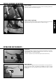
INTRODUCTION » We would like to congratulate you on your purchase of a KTM motorcycle. You are now the owner of a state-of-the-art sports motorcycle that guarantees to bring you lots of fun and enjoyment, provided that you clean and maintain it appropriately.
IMPORTANT » INTENDED PURPOSE KTM sports motorcycles are designed and constructed to resist the usual wear and tear of normal use in competitions. The motorcycles comply with the regulations and categories currently in effect with the leading international motorcycle associations. THE XC/XC-W MODELS ARE PROHIBITED ON PUBLIC ROADS. ENGLISH 2 The EXC and EXC-E models are only allowed on public roads in the original homologated (throttled) version. Without this performance restriction (i.e.
IMPORTANT » WARRANTY The service work specified in the "Lubrication and Maintenance Schedule" must be performed by a KTM workshop and recorded in the service manual otherwise claims under the warranty shall become void. No claims can be filed under the warranty for damage or consequential damage caused by manipulations or conversions to the motorcycle.
TABLE OF CONTENTS » Page SERIAL NUMBER LOCATIONS . . . . . . . . . . . . . . . . . . . .5 Chassis number . . . . . . . . . . . . . . . . . . . . . . . . . . . .5 Engine number, engine type . . . . . . . . . . . . . . . . . . . .5 ENGLISH 4 OPERATION INSTRUMENTS . . . . . . . . Clutch lever . . . . . . . . . . . . . . . . . . Hand brake lever . . . . . . . . . . . . . . . Electronic speedometer . . . . . . . . . . Indicator lamps (EXC) . . . . . . . . . . . Short circuit button . . . . . . . . . . . . .
SERIAL NUMBER LOCATIONS » Chassis number The chassis number is stamped on the right side of the steering head tube. Enter this number in the field on page no 1. The engine number and the engine type are stamped into the left side of the engine below the engine sprocket. Enter this number on page 1. ENGLISH Engine number, engine type 5 OPERATION INSTRUMENTS » Clutch lever The clutch lever [1] is located on the left side of the handlebars.
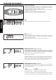
OPERATION INSTRUMENTS » Electronic speedometer The display in the electronic speedometer is activated as soon as you press a button on the speedometer or an impulse is received from the wheel sensor. The display lights up when the engine is running. The display is cleared if no button is pressed for 1 minute or no impulse is received from the wheel sensor. The | button is used to change between display modes. The + and – buttons are used to control various functions.
OPERATION INSTRUMENTS » Activating and deactivating display modes In the display mode SPEED/H, press and hold the | button for 3 seconds to access the SETUP menu. The active functions will be displayed. The blinking function can be activated by pressing the + button and deactivated by pressing the – button. Press and hold the | button 3 seconds to store the settings. If no button is pressed for 20 seconds, the setting will be stored automatically and the display will return to the SPEED/H mode.
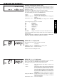
OPERATION INSTRUMENTS » LAP / LAP display mode (to view lap times) The LAP/LAP display mode will only be shown if lap times have been stored and the front wheel has stopped. It will display the lap number and the stopped lap time in hours, minutes and seconds. Press the + button to access the next lap time. To clear all of the stored lap times, hold the | button for 3 seconds in the SPEED/LAP mode. + button – button briefly press | button hold | button 3 secs.
OPERATION INSTRUMENTS » SPEED / S1 display mode (stop watch 1) S1 shows the traveling time based on TR1 and continues to run whenever it receives impulses from the wheel sensor. The calculation of this figure is activated by the first impulse received from the wheel sensor and stops 3 seconds after the last impulse is received. + button – button briefly press | button hold | button 3 secs. no function no function changes to the next display mode clears the TR1, S1, A1 figures S2 is a manual stop watch.
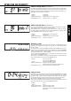
Motorcycle is driving Motorcycle is standing OPERATION INSTRUMENTS » X OVERVIEW OF THE ELECTRONIC SPEEDOMETER FUNCTIONS display briefly press + button briefly press – button briefly press | button hold | button 3 secs.
OPERATION INSTRUMENTS » 3 2 Combination switch (EXC/EXC Six Days) The light switch has 2, respectively 3 switch positions. [A] = Light off (this function is not available in all models) [B] = Low beam on [C] = High beam on You may use button [2] to actuate the horn. The red short circuit button [3] serves to switch off the engine. Leave the switch pressed until the engine stops. A B C Headlamp switch (XC-W) In this model the headlamp is switched on with the pull switch [4].
OPERATION INSTRUMENTS » Emergency OFF switch (EXC-E Australia) The red emergency-OFF switch [1] is arranged adjacent to the throttle grip. In this position, the E-starter is operational and the engine can be started. 1 In this position, the E-starter and ignition circuits are interrupted.The E-starter cannot be actuated, and the engine will not start, not even if you attempt to start it with the kickstarter. 2 Pushing the black starter button [2] will actuate the E-starter.
OPERATION INSTRUMENTS » Shift lever The shift lever is mounted on the left side of the engine. The position of the gears is shown in the illustration. Neutral, or the idle speed, is located between first and second gear. 2,3,4,5, (6) N 1 The kickstarter is mounted on the left side of the engine. Its upper part can be swivelled. ENGLISH Kickstarter 13 Foot brake pedal The foot brake pedal is disposed in front of the right foot rest.
OPERATION INSTRUMENTS » Compression damping of fork (XC) Hydraulic compression damping determines the reaction when the fork is compressed. The degree of compression can be adjusted with adjusting screws at the top of the fork legs. Turn the screw [1] clockwise to increase damping, turn it counterclockwise to reduce damping during compression.
OPERATION INSTRUMENTS » Compression damping of shock absorber STANDARD LOW-SPEED SETTING: – Turn the adjusting screw [1] to the limit in a clockwise direction using a screwdriver . – Unscrew the respective number of clicks for the specific type of shock absorber in a counterclockwise direction. Typ WP Suspension 12187D02 . . . . .15 clicks Typ WP Suspension 12187D04 . . . . .15 clicks Typ WP Suspension 12187D27 . . . . .15 clicks Typ WP Suspension 12187D28 . . . . .15 clicks Typ WP Suspension 12187D33 . .
GENERAL TIPS AND WARNINGS FOR STARTING THE MOTORCYCLE » Instructions for your first ride ENGLISH 16 – Make sure the work for the "pre-delivery inspection" was performed by your authorized KTM workshop. The DELIVERY CERTIFICATE and SERVICE MANUAL will be handed over when you pick up your vehicle. – Thoroughly read the whole instruction manual before starting for your first tour. – Familiarize yourself with the controls.
DRIVING INSTRUCTIONS » What you should check before each start When you start off, the motorcycle must be in a perfect technical condition. For safety reasons, you should make it a habit to perform an overall check of your motorcycle before each start. The following checks should be performed: 1 CHECK TRANSMISSION OIL LEVEL Too little transmission oil leads to premature wear and will ultimately destroy gear wheels and parts of the shift mechanism.
DRIVING INSTRUCTIONS » Starting when the engine is cold 1 2 3 4 5 6 ENGLISH 18 Open fuel tap Turn on emergency OFF switch Swing up the side stand Put the gear in neutral Activate cold-starting aid (choke) Leave throttle closed or open it no more than 1/3 and kick down kickstarter vigorously all the way. – For starting always put on your motorcycle boots to avoid injuries. You could slip off the kickstarter or the motor could kick back and fling your foot upwards.
DRIVING INSTRUCTIONS » Shifting/Riding – After falling with the motorcycle, check all its functions thoroughly before using it again. – A twisted handlebar must always be replaced. Do not adjust the handlebar, it will lose stability. – High rpm rates when the engine is cold have an adverse effect on the life of your engine. We recommend you run the engine in a moderate rpm range for a few miles giving it a chance to warm up. After that no further precautions in this respect need to be taken.
ENGINE CARBURETOR ADD-ON-PARTS at least once a year z z z z Check spark plugs, adjust distance between electrodes z Renew spark plugs z Clean the spark-plug connector and check for a tight fit z z z z Check the screws on the kick starter and shift lever for a tight fit z z z Check the carburetor connection boot and intake flange for cracks or leaks z Check idle speed setting z Check that vent hoses are not damaged or bent z z z z z z z z z Check cooling system for leaks, chec
C/H Clean and adjust carburetor Check the reed-type intake valve for wear C C/H C C/H Check the wear on the clutch disks and length of the clutch springs C C/H C C/H Check the cylinder and piston for wear C C/H C C/H C/H C/H C C/H Check function of exhaust control Check piston pin bearing C/H C C/H C/H Replace the crankshaft main bearings Replace the conrod bearings C C/H Check the entire transmission, the shift mechanism and bearings C C/H Complete maintenance of fork C C H
ENGINE z CARBURETOR z z Check spark plugs, adjust distance between electrodes z Renew spark plugs z Clean the spark-plug connector and check for a tight fit z z z z Check the screws on the kick starter and shift lever for a tight fit z z z z z z z z z z z z z z z z Check the carburetor connection boot and intake flange for cracks or leaks z Check idle speed setting z Check that vent hoses are not damaged or bent z Check cooling system for leaks, check quantity of antifreez
C/H Clean and adjust carburetor C/H Replace the throttle slide, jet needle, float needle valve, needle nozzle Check the reed-type intake valve for wear C C/H C C/H C C/H Check the wear on the clutch disks and length of the clutch springs C C/H C C/H C C/H Check the cylinder and piston for wear C C/H C C/H C C/H Check function of exhaust control Check piston pin bearing C/H C/H C/H C/H C/H C/H C C/H C Replace the crankshaft main bearings C/H C C/H C/H H Replace the conrod bea
MAINTENANCE WORK ON CHASSIS AND ENGINE » Maintenance and adjusting work marked with an asterisk * requires expert skills and technical know-how. For your own safety, always have such work performed by a specialized KTM dealer where your motorcycle will be optimally serviced by appropriately qualified, skilled staff. ENGLISH – If using a power washer, do not point the water jet at the electric components, plugs, cables, bearings, carburetor, etc.
MAINTENANCE WORK ON CHASSIS AND ENGINE » Basic suspension setup for the weight of the driver To achieve maximum handling performance and to prevent the fork, shock absorber, swing arm and frame from being damaged, the basic setup of the suspension components must be suitable for your weight. At delivery, KTM's offroad motorcycles are set to accommodate a driver weighing 75 bis 85 kg (wearing full protective clothing).
MAINTENANCE WORK ON CHASSIS AND ENGINE » TYPE SOFTER STANDARD HARDER 12187D02 63-250 66-250 69-250 12187D04 66-250 69-250 72-250 12187D27 60-250 63-250 66-250 12187D28 60-250 63-250 66-250 12187D33 63-250 66-250 69-250 12187D34 66-250 69-250 72-250 According to our experience, the damping rate of the compression stage can remain unchanged. The damping rate of the rebound stage can be reduced by a few clicks for a softer spring or increased by a few clicks for a harder spring.
MAINTENANCE WORK ON CHASSIS AND ENGINE » Cleaning the dust sleeves of the telescopic fork The dust-protection bellows [2] are to remove dust and coarse dirt particles from the fork tube. However, after some time, dirt may also get in behind the dust-protection bellows. If this dirt is not removed, the oil sealing rings located behind it may start to leak. Remove the screws [3] from the fork protector and allow the fork protector to hang down. Pry the dust boot out of the outer tubes and push down.
MAINTENANCE WORK ON CHASSIS AND ENGINE » Changing the fork offset (caster) XC/EXC Six Days * The fork offset [A] in the XC/EXC Six Days models (center fork legs - center steering head angle) can be set to either 18 or 20 mm. This allows you to optimize the handling to match the race course. A Remove the blind screw [1] to see which offset is set. If the mark [B] is in front, the offset is 18 mm. This setting will deliver more directional stability on fast race courses.
MAINTENANCE WORK ON CHASSIS AND ENGINE » Mount the lower triple clamp, upper steering head bearing, protection ring, O-ring, upper triple clamp and the blind screw. Tighten the collar screw on the lower triple clamp to 60 Nm. Mount the fork legs and tighten the clamp screws on the lower triple clamp to 12 Nm in 3 stages. Adjust the steering head bearing with zero clearance (see section on checking and adjusting the steering head support). Hold the middle clamp screw [A] in place with Loctite 243.
MAINTENANCE WORK ON CHASSIS AND ENGINE » Adapting the chain guide to the number of rear sprocket teeth (XC-W, EXC, EXC-E) C NOTE: The position of the chain guide must be adjusted due to the large number of rear sprockets available. Up to 44 teeth, insert the retaining screw on the chain guide in the lower hole [B], from 45 teeth in the upper hole [C]. B ENGLISH Loosen both screws on the chain guide and pull the chain guide off the swing arm.
MAINTENANCE WORK ON CHASSIS AND ENGINE » Correct chain tension 2 – If you don’t happen to have a torque wrench at hand, make sure you have the tightening torque corrected by a KTM dealer as soon as possible. A loose axle may lead to an unstable driving behavior of your motorcycle. – Tighten the collar nut with the required torque. A loose wheel spindle may lead to an unstable behavior of your motorcycle. 4 1 3 B NOTE: The large adjusting range of the chain adjusters (32mm / 1.
MAINTENANCE WORK ON CHASSIS AND ENGINE » General information about KTM disc brakes BRAKE CALIPERS: The brake calipers of this series use a „floating“ mount. This means that the brake calipers are not solidly attached to the caliper support, which enables them to ”float” for maximum braking contact.Secure the screws of the caliper support with Loctite 243 and tighten to 25 Nm.
MAINTENANCE WORK ON CHASSIS AND ENGINE » Changing the basic position of the hand brake lever min. 3 mm 1 You can change the basic position of the hand brake lever with the adjusting screw [1]. The position of the pressure point (the resistance you feel on the hand brake lever when the brake pads are pressed against the brake disk) can be adjusted for any hand size. Models without front brake light switch: When you push the hand brake lever forwards, you must have at least 3 mm free travel.
MAINTENANCE WORK ON CHASSIS AND ENGINE » Replacing the front brake pads * Press the brake caliper toward the brake disk, to put the brake piston in its basic position. Remove clips [1] and pull out bolt [2]. Remove brake pads from the brake caliper. Clean the brake caliper and the brake caliper support with compressed air. Check the sleeves of the guide bolts for damage, and grease guide bolts if necessary. Mount the right brake pad and fix it with the bolt.
MAINTENANCE WORK ON CHASSIS AND ENGINE » Changing the basic position of the foot brake pedal * 4 To change the basic position of the foot brake lever, loosen the counternut [1] and turn the stop screw [2] as needed. Be sure to adjust the free travel of the foot brake lever. Measured on the outside, the foot brake lever should have 3-5 mm free travel before the piston rod moves the piston in the foot brake cylinder (you will feel the stronger resistance of the foot brake lever).
MAINTENANCE WORK ON CHASSIS AND ENGINE » Dismounting and mounting the front wheel To remove the front wheel, jack the motorcycle up on its frame so that the front wheel no longer touches the ground. Loosen the collar screw [1] and the clamping screws [2] on both fork leg axle passages. Unscrew the collar screw approx 8 turns, press on the collar screw with your hand to push the wheel spindle out of the fork leg axle passage and remove the collar screw.
MAINTENANCE WORK ON CHASSIS AND ENGINE » Dismounting and mounting the rear wheel Jack the motorcycle up on its frame so that the rear wheel no longer touches the ground. Remove the collar nut [1], remove the chain tensioner [2] and pull out the wheel spindle [3] until you can push the rear wheel forwards. Take the chain off the rear sprocket, pull out the wheel spindle and carefully remove the rear wheel from the swing arm.
MAINTENANCE WORK ON CHASSIS AND ENGINE » Checking spoke tension The correct spoke tension is very important for the stability of the wheels and thus for riding safety. A loose spoke causes the wheel to become unbalanced and before long other spokes will have come loose. Check spoke tension, especially on a new motorcycle, at regular intervals. For checking, tap on each spoke with the blade of a screwdriver (see photo). A clear tone must be the result. Dull tones are indicators of loose spokes.
MAINTENANCE WORK ON CHASSIS AND ENGINE » Battery The battery is located under the seat and is maintenance-free. Maintenance-free means you will not need to check the acid level. Clean the battery terminals regularly and grease with acid-free grease if necessary. The charge condition and type of charge are very important for the battery's service life. TO REMOVE THE BATTERY: First disconnect the negative pole, then the positive pole from the battery. Detach the rubber band [1] and remove the battery.
MAINTENANCE WORK ON CHASSIS AND ENGINE » Fuse A The fuse [1] is located in the starter relay of the E-starter [2] underneath the left side paneling. Having removed the left side paneling, the air box cover and the protection cover [A], you will be able to see the fuse. The following loads are connected to it: – E-starter system – horn – flasher lights – electronic speedometer 2 The starter relay also contains a (10 amp) spare fuse [3]. ENGLISH 1 Replace a blown fuse only with an equivalent one.
MAINTENANCE WORK ON CHASSIS AND ENGINE » Checking the coolant level The coolant should be 10 mm (0.4 in) above the radiator fins when the engine is cold (see diagram). In the event of the coolant being drained, always fill and bleed the system. 10 mm when engine ist cold If possible, always check the level of cooling liquid when the engine is cold. If you have to open the radiator cap when the engine is hot, use a rag to cover the cap and open slowly to release pressure.
MAINTENANCE WORK ON CHASSIS AND ENGINE » Exhaust system * If the end cap [1] can be removed, the silencer is filled with glass-fiber yarn. Have the filling checked regularly by an authorized KTM workshop (see Lubrication and Service Chart). The insulating material fibers escape through the holes in the perforated pipe with time, causing the silencer to “burn out”. In addition to causing a higher noise-level, it will also affect the power characteristic.
MAINTENANCE WORK ON CHASSIS AND ENGINE » Bleeding the hydraulic clutch * 1 2 The clutch control needs to be bled as soon as the resistance in the clutch lever starts to feel unresponsive. You will need to use a bleeding syringe (special tool). Please note that Motorex 75 clutch fluid must be used for the 125/200 models and Motorex DOT. 5.1 brake fluid for the 250/300 models. Both are available from your KTM dealer.
MAINTENANCE WORK ON CHASSIS AND ENGINE » Definitions 2 Mixture too rich: Too much fuel in proportion to air. Mixture too lean: Not enough fuel in proportion to air. 1 Idling range A main jet jet needle D ENGLISH C B A jet needle Opening up B idle jet throttle valve Engine behavior when the throttle opens. The idle jet and the shape of the throttle valve influences this range.
MAINTENANCE WORK ON CHASSIS AND ENGINE » Draining the float chamber of the carburetor Following every wet-cleaning procedure, the float chamber of the carburetor should be drained in order to remove any water that may have penetrated into it. Water in the float chamber leads to engine malfunction. Make sure you do this while the engine is cold. Close the fuel tap, and place a cloth under the carburetor, which is capable of absorbing the leaking fuel. Unscrew the plug [1] and clean it with compressed air.
MAINTENANCE WORK ON CHASSIS AND ENGINE » Adjusting the engine characteristic via the auxiliary spring (250/300) * The engine characteristic can be modified through various thicknesses of the auxiliary spring [1]. An auxiliary spring designed for „good driveability“ (smooth power application) is mounted in the condition at delivery. One of the auxiliary springs can be mounted if you prefer an „even smoother power application“ or an „aggressive engine characteristic“.
MAINTENANCE WORK ON CHASSIS AND ENGINE » Check transmission oil level (125/200) In order to check the transmission oil level the control screw [1] on the clutch cover is to be removed. Oil should just barely escape from the inspection opening when the motorcycle is in an upright position. If necessary, remove the plug [2] and top up with oil (e. g. Motorex Top Speed 4T 15W50). 1 Transmission and clutch will be subjected to excessive wear and tear if you use too little or low grade oil.
CLEANING » Clean your motorcycle regularly in order to maintain the beauty of its plastic surfaces. The best manner would be to use warm water that has been mixed with a normal brand-name washing detergent and a sponge. The hard dirt can be removed before washing with the help of a soft water jet. If using a power washer, do not point the water jet at the electric components, plugs, cables, bearings, carburetor, etc.
49 ENGLISH
TECHNICAL SPECIFICATIONS – CHASSIS 125 EXC/SIX DAYS, 200 XC/XC-W/EXC 2008» ENGLISH 50 CHASSIS 125/200 XC/XC-W/EXC/EXC SIX DAYS Frame Central chrome-moly-steel frame Fork 125/200 XC-W/EXC/EXC Six Days 200 XC WP Suspension – 4860 MXMA PA (Open Cartridge) WP Suspension – 4860 MXMA CC (Closed Cartridge) Wheel travel front/rear 300/335 mm (11.8/13.2 in) Rear suspension WP Suspension – 5018 PDS DCC Front brake Disc brake with wave carbon-steel brake disc Ø 260 mm (10.
TECHNICAL SPECIFICATIONS – CHASSIS 125 EXC/SIX DAYS, 200 XC/XC-W/EXC 2008» STANDARD ADJUSTMENT – FORK 125/200 XC-W/EXC WP 4860 MXMA PA 14187D02 125 EXC Six Days WP 4860 MXMA PA 14187D33 200 XC WP 4860 MXMA CC 14187D27 Compression adjuster 22 clicks 20 clicks 20 clicks Rebound adjuster 22 clicks 22 clicks 21 clicks Spring 432.505.00.040W 432.505.00.042W 432.455.00.
TECHNICAL SPECIFICATIONS – ENGINE 125 EXC/EXC SIX DAYS, 200 XC/XC-W/EXC 2008» ENGINE 125 EXC/EXC SIX DAYS Design Liquid-cooled, single-cylinder, two-stroke engine with intake and exhaust control Piston displacement 124.8 ccm 193 ccm Bore / stroke 54 / 54.5 mm (2.126 / 2.145 in) 64 / 60 mm (2.52 / 2.362 in) Fuel unleaded fuel with at least RON 95 (USA = Premium RON 91), mixed with high grade two stroke oil Oil / gasoline ratio 1:60 when using high grade, two- stroke oil (Motorex Cross Power 2T).
TECHNICAL SPECIFICATIONS – ENGINE 125 EXC/EXC SIX DAYS, 200 XC/XC-W/EXC 2008» 125 EXC EU 4.
TECHNICAL SPECIFICATIONS - CHASSIS 250/300 XC/XC-W/EXC-E/EXC-E SIX DAYS 2008» ENGLISH 54 CHASSIS 250 XC/XC-W/EXC/EXC SIX DAYS Frame Central chrome-moly-steel frame Fork 250/300 XC 250 XC-W/EXC/EXC Six Days 300 XC-W/EXC-E/EXC-E Six Days WP Suspension – 4860 MXMA CC (Closed Cartridge) WP Suspension – 4860 MXMA PA (Open Cartridge) WP Suspension – 4860 MXMA PA (Closed Cartridge) Wheel travel front/rear 300/335 mm (11.8/13.
TECHNICAL SPECIFICATIONS - CHASSIS 250/300 XC/XC-W/EXC-E/EXC-E SIX DAYS 2008» STANDARD ADJUSTMENT – FORK 250/300 XC-W/EXC/EXC-E 250/300 EXC-E EXC-E SIX DAYS 250/300 XC WP 4860 MXMA PA WP 4860 MXMA PA WP 4860 MXMA CC 14.18.7D.04 14.18.7D.34 14.18.7D.28 Compression adjuster 22 clicks 24 clicks 20 clicks Rebound adjuster 20 clicks 22 clicks 21 clicks Spring 432.505.00.042W 432.505.00.044W 432.455.00.
TECHNICAL SPECIFICATIONS – ENGINE 250 XC/XC-W/EXC/EXC SIX DAYS 2008» ENGLISH ENGINE 250 XC Design Liquid-cooled single-cylinder two-stroke engine with KTM Twin Valve Control exhaust system and KTM Torque Chamber Piston displacement 249 ccm Bore / stroke 66.4 / 72 mm (2.62 / 2.84 in) Fuel unleaded fuel with at least RON 95 (USA = Premium RON 91), mixed with high grade two stroke oil (Motorex Cross Power 2T) Oil / gasoline ratio 1:60 when using high grade, two- stroke oil.
TECHNICAL SPECIFICATIONS – ENGINE 250 XC/XC-W/EXC/EXC SIX DAYS 2008» 250 XC 250 XC-W 250 EXC SIX DAYS 250 EXC AUS 250 EXC EU Carburetor Keihin PWK 36S AG Keihin PWK 36S AG Keihin PWK 36S AG Keihin PWK 36S AG Carburetor setting mark FK022 FK023 3600B FK025 Main jet 168 (170) 165 (162) 160 (162,165) 115 (162, 165) Idling jet 35 35 35 38x38 (35) Starting jet 85 85 85 50 (85) Jet needle N8RH (N8RG) N8RW (N8RH, N8RJ) N3CJ (N8RH, N8RJ, N8RW, N2ZJ, N2ZWG) N84K (N8RH, N8RJ, N8RW, NO
TECHNICAL SPECIFICATIONS – ENGINE 300 XC/XC-W/EXC-E/EXC-E SIX DAYS 2008» ENGLISH 300 XC Design Liquid-cooled single-cylinder two-stroke engine with KTM Twin Valve Control exhaust system and KTM Torque Chamber Piston displacement 293 ccm Bore / stroke 72 / 72 mm (2.84 / 2.84 in) Fuel unleaded fuel with at least RON 95 (USA = Premium RON 91), mixed with high grade two stroke oil (Motorex Cross Power 2T) Oil / gasoline ratio 1:60 when using high grade, two- stroke oil.
TECHNICAL SPECIFICATIONS – ENGINE 300 XC/XC-W/EXC-E/EXC-E SIX DAYS 2008» 300 XC 300 XC-W 300 EXC-E SIX DAYS 300 EXC-E AUS 300 EXC-E EU Carburetor Keihin PWK 36S AG Keihin PWK 36S AG Keihin PWK 36S AG Carburetor setting mark FK024 3600B FK026 Main jet 165 (162) 160 (162,165) 115 (162, 165) Idling jet 35 35 38x38 (35) Starting jet 85 85 50 (85) Jet needle N2ZJ (N2ZW) N3CJ (N8RH, N8RJ, N8RW, N2ZJ, N2ZWG) N84K (N2ZJ, N2ZW, NOZG) Needle position from top IV I III (IV) Throttle valve
SCHALTPLAN » WIRING DIAGRAMM ENGLISH 60
ENGLISH SCHALTPLAN » WIRING DIAGRAMM 61
SCHALTPLAN » WIRING DIAGRAMM ENGLISH 62
ENGLISH SCHALTPLAN » WIRING DIAGRAMM 63
SCHALTPLAN » WIRING DIAGRAMM l i g h t sw i t c h high/low beam switch horn switch ENGLISH cable c o lo r re cable c olor br bu ye gn wh L I G HT O F F HORN P.LIGHT OFF LO HI 64 P.
SCHALTPLAN » WIRING DIAGRAMM DEUTSCH Batterie Lüftermotor Fernlichtkontrolle Blinkerkontrolle Blinkerrelais Blinkerschalter vorderer Bremslichtschalter Generator Handle bar switch for multi-func.
SCHALTPLAN » WIRING DIAGRAMM ENGLISH Battery Cooling fan Driving light lamp Flasher relay Flasher control lamp Flasher switch Front brake switch Generator ENGLISH 66 FRANCAIS Batterie Ventilateur temoin feu route Relais de clignotants temoin de clignoteur buton de clignotants Contacteur de frein avant Alternateur Handle bar switch for multi-func.
VERGASERTABELLE » CARBURETOR TABLE VERGASERREGULIERUNG CARBURETOR SETTING 125 EXC/EXC SIX DAYS 2008 KEIHIN PWK 36S AG TEMPERATUR - 20°C bis -7°C - 6°C bis 5°C TEMPERATURE -2°F to 20°F 19°F to 41°F 6°C bis 15°C 16°C bis 24°C 25°C bis 36°C 37°C bis 49°C 42°F to 60°F 61°F to 78°F 79°F to 98°F 99°F to 120°F LSO LD NADEL POS HD ASO IJ NEEDLE POS MJ 1 45 NOZE 4 170 1,5 45 NOZE 3 168 1,5 42 NOZF 3 165 2 40 NOZF 2 162 2 38 NOZG 2 160 LSO LD NADEL POS HD ASO IJ NEEDLE POS MJ 1 48 NOZE 4 170 1 45
VERGASERTABELLE » CARBURETOR TABLE VERGASERREGULIERUNG CARBURETOR SETTING 200 XC/XC-W/EXC 2008 KEIHIN PWK 36S AG MEERESHÖHE ALTITUDE TEMPERATUR - 20°C bis -7°C - 6°C bis 5°C TEMPERATURE -2°F to 20°F 19°F to 41°F 6°C bis 15°C 16°C bis 24°C 25°C bis 36°C 37°C bis 49°C 42°F to 60°F 61°F to 78°F 79°F to 98°F 99°F to 120°F LSO LD NADEL POS HD ASO IJ NEEDLE POS MJ 1 42 NOZH 4 162 1 42 NOZH 3 160 1,5 42 NOZI 3 158 1,5 40 NOZI 2 155 2 40 NOZJ 2 152 LSO LD NADEL POS HD ASO IJ NEEDLE POS MJ 1 45 NO
VERGASERTABELLE » CARBURETOR TABLE VERGASERREGULIERUNG CARBURETOR SETTING 250 XC 2008 KEIHIN PWK 36S AG TEMPERATUR - 20°C bis -7°C - 6°C bis 5°C TEMPERATURE -2°F to 20°F 19°F to 41°F 6°C bis 15°C 16°C bis 24°C 25°C bis 36°C 37°C bis 49°C 42°F to 60°F 61°F to 78°F 79°F to 98°F 99°F to 120°F LSO LD NADEL POS HD ASO IJ NEEDLE POS MJ 1 35 N8RH 4 168 1 35 N8RH 3 168 1,5 35 N8RW 3 165 1,75 35 N8RW 2 162 2 35 N8RJ 2 160 LSO LD NADEL POS HD ASO IJ NEEDLE POS MJ 1 35 N8RG 4 170 1 35 N8RH 4 168 1
VERGASERTABELLE » CARBURETOR TABLE VERGASERREGULIERUNG CARBURETOR SETTING 250 XC-W/EXC/EXC-SIX DAYS 2008 KEIHIN PWK 36S AG MEERESHÖHE ALTITUDE TEMPERATUR - 20°C bis -7°C - 6°C bis 5°C TEMPERATURE -2°F to 20°F 19°F to 41°F 6°C bis 15°C 16°C bis 24°C 25°C bis 36°C 37°C bis 49°C 42°F to 60°F 61°F to 78°F 79°F to 98°F 99°F to 120°F LSO LD NADEL POS HD ASO IJ NEEDLE POS MJ 1 35 N8RW 4 165 1 35 N8RW 3 165 1,5 35 N8RJ 3 162 1,5 35 N8RJ 2 160 2 35 N8RK 2 158 LSO LD NADEL POS HD ASO IJ NEEDLE POS M
VERGASERTABELLE » CARBURETOR TABLE VERGASERREGULIERUNG CARBURETOR SETTING 300 XC/XC-W/EXC/EXC-SIX DAYS 2008 KEIHIN PWK 36S AG TEMPERATUR - 20°C bis -7°C - 6°C bis 5°C TEMPERATURE -2°F to 20°F 19°F to 41°F 6°C bis 15°C 16°C bis 24°C 25°C bis 36°C 37°C bis 49°C 42°F to 60°F 61°F to 78°F 79°F to 98°F 99°F to 120°F LSO LD NADEL POS HD ASO IJ NEEDLE POS MJ 1 35 N2ZJ 4 165 1 35 N2ZJ 3 165 1,5 35 N2ZJ 3 162 1,5 35 N2ZK 2 160 2 35 N2ZK 2 158 LSO LD NADEL POS HD ASO IJ NEEDLE POS MJ 1 35 N2ZW 4 16
INDEX » ENGLISH 72 Page Activating and deactivating display modes . . . . . . . . .7 Adjusting the engine characteristic via the auxiliary spring .45 Adjusting the engine characteristic via the ignition curve . .44 Basic suspension setup for the weight of the driver . . .25 Battery . . . . . . . . . . . . . . . . . . . . . . . . . . . . . . . . . .39 Bleeding the hydraulic clutch . . . . . . . . . . . . . . . . .43 Braking . . . . . . . . . . . . . . . . . . . . . . . . . . . . . . . . .
OWNER’S MANUAL 2008 125 EXC, EXC SIX DAYS 200 XC, XC-W, EXC 250 XC, XC-W, EXC, EXC SIX DAYS 300 XC, XC-W, EXC-E, EXC-E SIX DAYS *3211226en* 3211226en 3211226en 5/2007 FOTO: MITTERBAUER KTM Group Partner KTM-Sportmotorcycle AG A–5230 Mattighofen www.ktm.