
User Manual

10
menu.
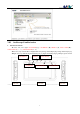
Calibrat Instrument calibration (make
sure CH_A is ground connected)
Press (―…+) to confirm, press
(■) to calibrate.
IX Application Examples:
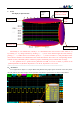
1. Example One:Measure simple signals
Observe one unknown signal in a circuit, measure & display the frequency & peak-to-peak value of the signal.
Please operate according to following steps:
Connect the probe of CH_A/CH_B to the detection point of the circuit.
Set CH(A)/CH(B) as AUTO mode, DC coupling, adjust the(horizontal) time calibration and (vertical) voltage
calibration, make sure the signal displays clearly.
Adjust THR value to make the display of signals stable.
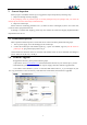
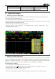
Press(●), analyze signal parameters, e.g.:Vpp(peak-to-peak voltage), RMS(average value of
voltage),FRQ(frequency) and so on.
Take the following figure as an example:
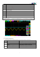
2. Example Two: Acquire a single signal
It’s the superiority and feature of digital oscilloscope to easily acquire non-periodic signals like impulsion
and sentus. To acquire a single signal, you need a priori knowledge of it to set trigger level & trigger edge. E.G. if
impulsion is a TTL PWL logic signal, trig level should be set as 2V, trig edge as rising edge trig. If the signal is
not stable, it’s suggested to observe in a normal triggering mode to define trig level & trig edge.
Operation steps are as follows:
Connect the probe of CH_B to detection point of the circuit.
Set the triggering: set J as (rising edge trig), F as SINGL(single trig), trig setting: DC coupling.
Adjust horizontal time level and vertical scale to proper range.
Adjust K position THR, adjust to proper trig level.
Press (||), wait for proper trig signal to appear. If a signal reaches preset trig level, sample & display it.