
User Manual

6
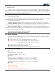
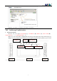
2. Screen
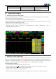
The display is depicted below:
Horizontally A—I is channel area; vertically J—T is measurement area. You can move cursor within A—G
by scrolling (…); change selection by scrolling (―…+); move cursor between upper & lower menus by
pressing (―…+). When cursor is in G Position, press (―…+) to move it within G—I; and press (▲) to move
cursor between channel area & measurement area. Each menu has the same color as its corresponding channel:
Channel A ( blue), Channel B( yellow), Channel C( purple), Channel D( green), Common menu is orange.
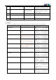
U—X is parameter area, U position shows parameters for THR, V1 & V2 to choose; V position is the
preferred parameter of (●) button; W position is
△
T=T2-T1, X position is
△
V=V1-V2
---------------------------------------------------------------------------------------------------------------------
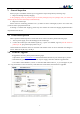
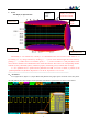
2.1、Parameters
As in figure below, adjust G—I,output 1KHz from [WAVE OUT],input square waveform of 50% duty factor
into CH_B,Short press (●) to display current parameter.Annotations of parameters are shown in table below:
Display the position
of current waveform
Trigger
point
cache
depth
Channel Area
Parameter Area
Measurement Area