
Installation Guide
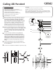

3b.
3a.
INSTALLATION SHEET
CH9621
Ceiling LED Pendant
START FROM HERE
•
Make sure power is completely off at the fuse box.
•
Have your fixture installed by a qualified licensed electrician
•
Prepare everything in a clear area.
•
Wear gloves at all times during this installation.
•
Read instructions carefully before you start assembly.
•
Keep this instruction sheet for future reference.
Technical Support: 1-877-452-6858
Please Note:
• For dimming, a TRIAC or ELV type of dimmer is required.
CAUTION: CAUTION: HEAVY FIXTURE, THE JUNCTION BOX
NEEDS TO BE REINFORCED BEFORE INSTALLATION. ALL MOUNTING SCREWS
MUST SCREW INTO A MINIMUM OF 1” OF WOOD BEHIND THE DRYWALL. DO NOT
MOUNT THIS FIXTURE JUST TO DRYWALL
. (Be sure all wood that you screwed into, is
secured to the cross beams/ceiling joists behind the drywall)
2b.
2a.
1a.
1b.
1e.
1c.
1d.
2c.
illustration 01
2d.
2e.
Match the thread with
the swivel (2d)
1.
You have now completed the installation of your fixture, enjoy.
Before you mount the canopy to the mounting plate, install
4-inch threaded rod (2e) in-between the swivel (2d) and the
extension rods (2c) and then secure the extension rods
(2c) to the canopy (2a). (see rear for the full DC driver
pre-install).
Push the glass (3a) down to the LED engine (3b) and
thread, turning clockwise. Repeat this step for the remain-
der, see map below.
You are now ready to mount the canopy (2a) to the
mounting plate (1c). Align the threaded screws (1d)
hanging downward from the mounting plate to the holes
inside the canopy (2a). Push the canopy up towards the
ceiling so the two screws point through the hole in the
canopy (2a). You can now screw on the decorative nuts
(2b) onto the threaded studs (1d) pointing through the
canopy.
Remove the fixture from its original packaging. Remove
the mounting plate (1c) from within the canopy (2a) by
removing the two decorative nuts (2b). Remove the
wires, aircraft cable and extension rods (2c) from canopy
(2a). To shorten or lengthen the fixture (3b) just remove
or add extension rods (2c) by threading clockwise for
adding and counter clockwise for removing. Secure the
mounting plate (1c) to the reinforced junction box (1a)
with the screws (1e) provided in the hardware package.
2.
3.
4.
5.
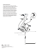
G
G
G
G
H
H
H
H
H
H
H
I
I
I
I
I
115
80
160