Satellite Television A Guide to TracVision G4 technical manual • KVH TracVision G4 • Installation Configuration Maintenance ® •
TracVision® G4 Wiring Quick Reference Guide Data Cable TracVision G4 can either receive power through the ADCU (as illustrated in the diagram) or directly from ship’s power if that is more convenient. Refer to "Alternate Method of Providing Power to the Antenna" on page 32 for details.
GyroTrac™ Advanced Digital Control Unit (ADCU) Menu Quick Reference Guide ADCU Primary Display Options See Section 3.2 for details Compass Displays* Pitch, Roll, Yaw Magnetic Heading ###.#° Pitch #.#° Roll #.#° Yaw #.#° Latitude/Longitude† Rate of Turn Mag/Hdg #.#° Rate/Sec #.#° Lat: Long: ## ## Antenna Displays Tracking ###.#° ##.#° #### SELECTED DISPLAY Mag/HDG ###.#° Select Installed Satellite A True/HDG ###.
Welcome to TracVision G4 TracVision G4 Technical Manual This manual provides detailed instructions on the proper installation, configuration, troubleshooting, and maintenance of the KVH TracVision G4 system. Complete instructions on how to use the TracVision G4 system is provided in the TracVision G4 User’s Guide.
TracVision® and KVH® are registered trademarks of KVH Industries, Inc. GyroTrac™ and TracNet™ are trademarks of KVH Industries, Inc. DVB® (Digital Video Broadcasting) is a registered trademark of the DVB Project. DIRECTV® is an official trademark of DIRECTV, Inc., a unit of GM Hughes Electronics. DISH Network™ is an official trademark of EchoStar Communications Corporation. ExpressVu is a property of Bell ExpressVu, a wholly owned subsidiary of Bell Satellite Services. Cetrek™ is a trademark of Cetrek USA.
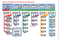
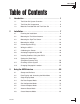
Table of Contents Table of Contents 1 2 3 54-0147 Introduction . . . . . . . . . . . . . . . . . . . . . . . . . . . . . . . . . .1 1.1 TracVision G4 System Overview . . . . . . . . . . . . . . . . . . . . .3 1.2 TracVision G4 Components . . . . . . . . . . . . . . . . . . . . . . . . .5 1.3 Materials Provided With the TracVision G4 . . . . . . . . . . . . .6 Installation . . . . . . . . . . . . . . . . . . . . . . . . . . . . . . . . . . .7 2.1 Planning the Installation . . . . . . . . . . . .
4 Troubleshooting . . . . . . . . . . . . . . . . . . . . . . . . . . . . . . .91 4.1 Troubleshooting Matrix . . . . . . . . . . . . . . . . . . . . . . . . . . . .93 4.2 Causes and Remedies for Common Operational Issues . . . . . . . . . . . . . . . . . . . . . . . . . . . . . . .94 4.3 GyroTrac-specific Issues . . . . . . . . . . . . . . . . . . . . . . . . . .
Introduction 1 – Introduction This section provides a basic overview of the TracVision G4 system. It explains how the system works and describes the function of each component. Contents 54-0147 1.1 TracVision G4 System Overview . . . . . . . . . . . . . . . . . . . . . . . . . . .3 1.2 TracVision G4 Components . . . . . . . . . . . . . . . . . . . . . . . . . . . . . . .5 1.3 Materials Provided With the TracVision G4 . . . . . . . . . . . . . . . . . . .
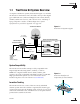
Introduction 1.1 TracVision G4 System Overview A complete satellite TV system, illustrated in Figure 1-1, includes the TracVision G4 antenna unit connected to the GyroTrac digital gyro-stabilized sensor, Advanced Digital Control Unit (ADCU), an IRD (satellite TV receiver), and a television set. A desktop or laptop computer is used to conduct diagnostics. System specifications are provided in Appendix A on page 123. Figure 1-1 TracVision G4 System Diagram TracVision G4 Antenna 11-16 VDC 3.5 - 4.
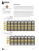
TracVision G4 Technical Manual Satellite Library Your TracVision G4 includes a pre-programmed satellite library of North American and European satellite services. When configuring the TracVision G4, you may choose a pair of satellites from the library to be active in the system and with your IRD. TracVision G4’s default satellite pairs are: N.
Introduction 1.2 TracVision G4 Components Your TracVision G4 system includes the following components: Antenna Unit The antenna unit houses the antenna positioning mechanism, low noise block (LNB), power supply, and control elements within a molded ABS radome. Weathertight connectors on the bottom of the baseplate join the power, signal, and control cabling from belowdecks units.
TracVision G4 Technical Manual 1.3 Materials Provided With the TracVision G4 Table 1-3 lists the components and materials in the TracVision G4 shipping carton. Table 1-3 TracVision G4 Packing List For lists of items supplied in the kitpacks, see Tables 2-3 and 2-4 on page 10. Component KVH Part No.
Installation 2 – Installation This section explains how to install, configure, and test the TracVision G4 system. Follow the simple procedures in this section sequentially to ensure a safe and effective installation. Contents 54-0147 2.1 Planning the Installation . . . . . . . . . . . . . . . . . . . . . . . . . . . . . . . . .9 2.2 Mounting the TracVision Antenna . . . . . . . . . . . . . . . . . . . . . . . . .15 2.3 Mounting the GyroTrac Sensor . . . . . . . . . . . . . . . . . . . . . . . . . .
Installation 2.1 Planning the Installation Who Should Install the TracVision G4 KVH recommends that a KVH-authorized technician install the TracVision G4 system. Installers should have experience installing electronic equipment on a vessel. Materials and Equipment Required for Installation Plan the entire installation before proceeding! Take into account antenna unit placement, cable running distances between units, and accessibility to the equipment after installation.
TracVision G4 Technical Manual • Table 2-2 Recommended ADCU-to-Ship’s Power Cable Specifications Power cable to connect the ADCU to ship’s power (Table 2-2 provides proper gauge and length specifications). Cable Length Cable Gauge to 50 ft (15 m) 14 AWG (1.5 mm2) +50 ft (+15 m) 12 AWG (2.5 mm2) Kitpack Contents The kitpacks packaged with your antenna unit and GyroTrac contain various hardware and other materials that will be needed to complete the TracVision system installation.
Installation Part Qty. Tie-wrap screw mount 6 Terminal strip connectors 5 Sensor module to ADCU power wire ferrite 1 #4-24 thread-forming screws 4 Table 2-4 GyroTrac Kitpack Contents (Continued) Choosing Component Locations The major considerations in locating the TracVision components are described below. Cable Lengths When determining component locations, keep in mind accessibility and cable lengths between units.
TracVision G4 Technical Manual Choosing the Best Location for the TracVision Antenna There are several factors to consider when choosing the location for the TracVision antenna. • Since the TracVision antenna requires a clear view of the southern sky to receive satellite signals, the ideal antenna site has an unobstructed view of the horizon/satellite all around. The less blockage, the better the system performs. • Keep the antenna clear of any obstructions above decks.
Installation Figure 2-2 Antenna Unit Dimensions 21" Max 54 cm The radome exterior is treated with a special finish selected for compatibility with the dome material and transparency to the satellite signals. Application of additional paints or finishes WILL degrade performance, potentially beyond acceptable limits. 19.3" 49 cm 9" (22.9 cm) 4.5" (11.4 cm) 4.5" (11.4 cm) 9" (23 cm) A full-size template of the baseplate mounting holes has been provided in Appendix B on page 127. 4 x 5/16" ( 8 mm) 19.
TracVision G4 Technical Manual Choosing the Best Location for the GyroTrac Sensor • Ideally, the sensor module should be mounted as low as possible in the center of the vessel – but NOT in the bilge. • The mounting surface should be free of excessive vibration and flexing. • Maintain at least four feet (1.3 m) separation between the sensor module and any magnetized materials, large ferrous masses, cranes, engines, derricks, other antennas, cables carrying high amperage direct current, or battery banks.
Installation 2.2 Mounting the TracVision Antenna 1. Make sure that you have chosen a suitable mounting location based upon the guidelines in “Choosing the Best Location for the TracVision Antenna” on page 12. 2. Using the template provided in Appendix B on page 127 or the dimensions shown in Figure 2-3, lay out the four mounting bolt holes and cable access hole at the mounting site. Make certain that the “FWD” arrow is parallel with the vessel’s centerline and pointed toward the bow.
TracVision G4 Technical Manual 6. Remove and save the three screws securing the radome to the baseplate. Carefully lift the radome straight up until clear of the antenna assembly and set it aside in a safe place. If you bring the radome topside, be sure to secure it with a lanyard so that it does not fall overboard. 7. Remove the foam shipping restraint from the antenna unit. 8.
Installation 10. Position the baseplate assembly in place over the mounting holes and cable access, with the baseplate’s “Forward” arrow (shown in Figure 2-6) pointing toward the bow. Ensure that all holes line up and that the connectors are centered over the cable access. Make any necessary adjustments before seating the foam seal in place permanently. 11. Clean the mounting surface where the foam seal will be placed.
TracVision G4 Technical Manual 13. Place the antenna baseplate over the holes drilled in the foundation, ensuring the “Forward” label (shown in Figure 2-6) points toward the bow. When rotating the azimuth mechanism by hand, go slowly. Hitting the mechanical stops with excessive force will damage the azimuth limit switch. 14. At each of the four baseplate mounting holes, place a 1⁄4" flat washer on a 1⁄4"-20 bolt and insert the bolt into the hole from above, as shown in Figure 2-8.
Installation 2.3 Mounting the GyroTrac Sensor GyroTrac comes with the following two mounting brackets: Horizontal Sensor Bracket Attaches directly to the sensor module housing and must be used in all mounting arrangements Figure 2-9 Horizontal Sensor Bracket Vertical Sensor Bracket For mounting the sensor to a vertical surface These two brackets should enable you to place the sensor module as level as possible.
TracVision G4 Technical Manual Option 1 - Mounting the Sensor to a Horizontal Surface 1. Choose a mounting location based upon the guidelines in “Choosing the Best Location for the GyroTrac Sensor” on page 14. 2. Orient the sensor so that the forward reference on the end cap is pointed forward and is parallel to the vessel’s fore-and-aft axis (to ±5°). The proper orientation is illustrated in Figure 2-11. Figure 2-11 Proper Orientation of the Sensor Module RD W BO WA TO 5¡ 5¡ 3.
Installation 5. Insert #8 fiber washers into the mounting bracket’s four mounting holes on both sides of the mounting bracket (see Figure 2-12). T-nuts contained within sensor housing track Figure 2-12 Securing the Sensor Module and the Horizontal Sensor Bracket Flat washer, lock washer, and #10 screw #8 screw, flat washer, and 2 fiber washers 6. Insert #8 flat washers and #8 Phillips screws into the mounting bracket’s four mounting holes from above. Secure the bracket to the mounting surface. 7.
TracVision G4 Technical Manual Option 2 - Mounting the Sensor to a Vertical Surface 1. Choose a mounting location based upon the guidelines in “Choosing the Best Location for the GyroTrac Sensor” on page 14. 2. The module must be oriented so that the forward reference on the end cap is pointed forward and parallel to the vessel’s fore-and-aft axis (see Figure 2-11 on page 20).
Installation 6. Secure the vertical sensor bracket to the mounting surface with #8 Phillips screws and flat washers (see Figure 2-14). If you do not use the supplied #8 screws, be sure to use equivalent hardware that ensures secure mounting and minimum vibration. Figure 2-14 Mounting the Vertical Sensor Bracket #8 screw and washer 7. Position the horizontal sensor bracket over the mounting holes in the vertical sensor bracket, as shown in Figure 2-13. 8.
TracVision G4 Technical Manual 2.4 Mounting the ADCU Mount the ADCU using either of the following options: Option 1 - Velcro Fastening on a Horizontal Surface Option 2 - Flush-mounting The following sections describe how to mount the sensor for both of these options. Option 1 - Velcro Fastening on a Horizontal Surface When choosing a location, take into account the space required to route, position, and strain-relieve all cables that will be attached to the back of the ADCU.
Installation Option 2 - Flush-mounting 1. Choose a location based upon the guidelines in “Choosing the Best Location for the ADCU” on page 14. 2. A template has been provided in Appendix C on page 129 as a guide to mark and cut the proper hole for the flush mount bracket. Cut the hole and make certain the bracket and ADCU will fit easily. 3. Attach the flush mount bracket to the ADCU by loosening the two screws on the underside of the ADCU.
TracVision G4 Technical Manual 2.5 Connecting the IRD(s) For the TracVision system to work, you must connect the following cables to your satellite TV receiver(s) (IRDs): • RF Cable • Ground Wire Connecting the RF Cable(s) Each RF cable must be an RG-11 (75 ohms) or RG-6 (75 ohms) cable fitted with F-type connectors. The RF cable(s) should already be connected to the antenna baseplate (see Step 12 of Section 2.2., “Mounting the TracVision Antenna” on page 17).
Installation Option 3 - Connecting Three or More IRDs (North American Systems only) To connect three or four IRDs to the TracVision antenna, you will need to install an active multiswitch (Channel Master model 6214IFD or equivalent) between the antenna and the IRDs. Two RF cables should already be connected to the plugs labeled “RF1” and “RF2” on the base of the TracVision antenna. Figure 2-18 shows a typical wiring arrangement for three or four IRDs.
TracVision G4 Technical Manual Multiple Multiswitch Installation If you need to connect more than four IRDs to the TracVision antenna, you may carry out a multiple multiswitch installation, as shown in Figure 2-19.
Installation 2.6 Wiring the ADCU All other wiring for the TracVision system connects at the rear panel of the ADCU. Included in the GyroTrac kitpack are five terminal strip connectors with terminal connectors numbered 1 through 60 (see Figure 2-20). You will connect all wires to these terminal strip connectors first, then you will insert the connectors into the rear panel of the ADCU.
TracVision G4 Technical Manual Figure 2-21 ADCU Wiring SENSOR DATA FEED (to Antenna) Data Cable TXD- (Green/White) Antenna Ground (Black) NOT USED TXD+ (White/Green) Antenna Power (Red) +11-16 VDC TRACVISION POWER (to Antenna) Power Cable 48 47 46 45 44 43 42 41 40 39 38 37 Red Label PC RXD (Orange/White) DSS Ground (White/Orange) TRACVISION PORT (to/from Antenna) Data Cable DSS TXD (Gray/White) PC TO ANTENNA DATA LINES Data Cable PC TXD (White/Brown) DSS RXD (White/Gray) PC Ground (Brown/Whi
Installation Tips for Safe and Successful Wiring • When inserting a wire into a terminal connector, make certain that the wire insulation is not pinched in the connector. • After inserting and securing wire, tug gently to ensure that the connection is solid. • Position cables behind the ADCU so that they connect neatly to the terminal strips. • Do not tin (solder) the wire ends. • Each cable provided with the TracVision G4 should be routed and dressed before terminating at the ADCU.
TracVision G4 Technical Manual Connecting the Antenna Power Cable For single-switch convenience, the ADCU has been designed to serve as a junction box between ship’s power and the antenna unit. Connect the antenna power cable to the red ADCU terminal strip connector as shown in Figure 2-23.
Installation Connecting the GyroTrac Sensor Cable 1. Connect the connectorized end of the sensor cable to the GyroTrac sensor module. Twist until locked in place. Figure 2-24 GyroTrac Sensor Connector Sensor Cable Connector 2. Connect the other end of the sensor cable to the blue ADCU terminal strip connector as shown in Figure 2-25.
TracVision G4 Technical Manual Connecting External Devices to the ADCU (Optional) GyroTrac can be integrated with many types of onboard equipment, including autopilots, radars, remote displays, plotters, global positioning systems (GPS), and computers. All connections between the ADCU and external devices are made at the terminal strip connectors located on the rear of the ADCU.
Installation Connecting the Sine/Cosine Interface (Optional) The GyroTrac ADCU sine/cosine interface provides the following outputs: • sine • cosine • inverse sine • inverse cosine • reference voltage Green Label 1 2 3 4 5 6 7 8 9 Figure 2-26 Sine/Cosine ADCU Wiring 10 11 12 Sine Sine (inverted) Cosine Cosine (inverted) Ref Ground Because the reference voltage is a reference output, not an input, connecting this output to another reference output from an autopilot or other system will
TracVision G4 Technical Manual To adjust the GyroTrac reference to match the reference of the autopilot (or other system), connect a voltmeter to GyroTrac ADCU terminal (#8) and the reference terminal of the autopilot (or other system). Adjust the GyroTrac reference voltage as described in “Setting the Sine/Cosine Data Output” on page 69 until the voltmeter indicates 0 VDC. The sine/cosine interface should now operate with optimal precision.
Installation Connecting the ADCU to Vessel Power Short circuits may result in severe electrical shock or burns. Turn off vessel power and test the circuit to ensure that no power is present before connecting any power cables. Do NOT reapply power until all system wiring is completed and all terminal strip connectors are installed on the ADCU rear panel, as described in “Connecting the Terminal Strip Connectors to the ADCU” on page 38. The TracVision G4 system requires an 11-16 VDC power input.
TracVision G4 Technical Manual Connecting the Terminal Strip Connectors to the ADCU Now that you have connected all wires to the terminal strip connectors, insert the connectors into the ADCU’s rear panel as shown in Figure 2-29. Figure 2-29 Attaching the Terminal Strips to the ADCU & ' ! " # $ % Double-check all wiring. Be certain to plug terminal strips into the correct positions.
Installation Effective Strain Relief for ADCU Terminal Connections Due to both the potential number of wires that connect to the rear of the ADCU and the dynamic environment aboard ship, it is critical that the terminal connections be properly strain-relieved using tie-wraps (a number of which are included in the GyroTrac kitpack). Some things to consider when strain-relieving wires: • There should be no tension on the wires connecting to the terminal strips.
TracVision G4 Technical Manual 2.7 Calibrating the Sensor Every sensor module is calibrated at the factory in a perfectworld environment. However, hard and soft iron effects on your vessel can distort the local magnetic field, causing errors in the reported heading. These errors are minimized by mounting the sensor module in a suitable location and are further removed by GyroTrac’s autocalibration feature, which compensates for minor magnetic distortions.
Installation The Calibration Score Each calibration results in a calibration score that is stored in the system’s memory. Figure 2-32 Sample Calibration Score Screen Magnetic Environment Accuracy Calibration Update Number ACC CAL<1° MagEnv GOOD Cal# 3 Table 2-7 Possible Compass Accuracy Levels Accuracy (ACC) The ACC data indicates the degree of accuracy the GyroTrac will provide based on the quality of the last calibration. Table 2-7 lists the five possible accuracy levels.
TracVision G4 Technical Manual 2.8 Activating/Programming the IRD Before it can be used, your IRD must be activated and/or programmed, as described below. DIRECTV and DISH Network IRD Activation KVH makes it easy to activate your DIRECTV or EchoStar (DISH Network) IRD. Just call KVH at 1-888-584-4163 and ask for IRD Activation (Monday - Friday, 8:30 a.m. - 5:00 p.m. EST). For other options, please refer to the user manual that accompanied your IRD.
Installation Programming DSS Plus IRDs If you are using multiple DSS Plus IRDs and intend to shift from one satellite to another, only one of the IRDs can be configured as a two-satellite receiver. All other IRDs must be configured as onesatellite receivers. The two-satellite IRD will determine which satellite the antenna is tracking while the other receivers can watch any channels available via that satellite. Refer to your IRD owner’s manual for complete details on this process.
TracVision G4 Technical Manual 2.9 Table 2-9 Available Satellite Pairs – North America (North American LNB required) DSS_101 DSS_119 Installing Satellites Using the ADCU The TracVision G4 can track a variety of DVB-compatible and DIRECTV (DSS) satellites. The system contains a preprogrammed library of North American and European satellites. It also has two open slots that you may use to program two additional satellites of your choice. Tables 2-9 and 2-10 list the possible satellite pairs.
Installation Installing Your Selected Satellites To install your selected satellites as Satellite A and B, follow the steps below. 1. Apply power to the ADCU. 2. Following the startup sequence, press the center button until the “Control Antenna?” screen appears. Control antenna? Enter Next Return Figure 2-33 Control Antenna Screen 3. Press the ENTER button to access the Control Antenna Mode. 4. Press the center button until the “Install Satellite?” screen appears. Install satellite? Yes Next Return 5.
TracVision G4 Technical Manual Figure 2-35 Install Satellite Process Install Satellite? Yes Next Return - Latitude: Enter ##N + Proceed to "Setting Latitude and Longitude" Install A Yes Next Cancel - Longitude: Enter ###E + Selecting NEXT will cycle the display through all available satellites Install B Yes Next Cancel Installing sats Please wait Latitude: Longitude: Selecting NEXT will cycle the display through all satellites that can be paired with the selection for Satelli
Installation Programming User-defined Satellites The TracVision G4 satellite library has the capacity for two userdefined satellites in case you want to track a satellite that is not currently preprogrammed in the library. User-defined satellites can only be configured via the ADCU’s maintenance port.
TracVision G4 Technical Manual Connecting a PC to the ADCU Maintenance Port To program your user-defined satellites into the TracVision G4 satellite library, you need to connect a PC to the ADCU’s maintenance port. This procedure requires Windows Hyperterminal (or other terminal emulation software, such as PROCOMM). Use the settings appropriate to your application and follow the steps below. 1. Connect one end of the PC data cable to the DB9 maintenance port connector on the rear of the ADCU.
Installation Entering User-defined Satellite Data To configure your user-defined satellites, follow the steps below. 1. Using your PC’s terminal emulation program, type HALT ( indicates a carriage return/ENTER key). This command puts the antenna in Idle mode. 2.
TracVision G4 Technical Manual 5. Repeat Step 4 for each of the following transponder categories: • vertical high • vertical low • horizontal high • horizontal low right • left OR • TracVision G4 requires that the data fields for all transponder categories be provided.
Installation Installing User-defined Satellites via the Maintenance Port 1. Type HALT to put the antenna in Idle mode. 2. Enter the SATINSTALL parser command: Command: SATINSTALL, Where: = the name of your choice for Satellite A (for example: USER1) = the name of your choice for Satellite B (for example: USER2) If you only want to install and track one satellite, enter NONE as the name of Satellite B. 3.
TracVision G4 Technical Manual An Example of Configuring a User-defined Satellite (N. America) The following is an example of configuring the fictional YOURSAT 123 as the USER1 configured satellite. Prior to configuring this satellite or any others, be certain to get the most up-to-date information from one of the sources previously discussed. Table 2-14 Sample Satellite Configuration Data (North America) YOURSAT 123 at 122 West, DVB decoder, Circular Polarization LNB Right Frequency 12.
Installation An Example of Configuring a User-defined Satellite (Europe) The following is an example of configuring the fictional YOURSAT 123 as the USER1 configured satellite. Prior to configuring this satellite or any others, be certain to get the most up-to-date information from one of the sources previously discussed. Yoursat 123 at 7 West, DVB decoder, Linear Polarization LNB Horizontal High Frequency 11.
TracVision G4 Technical Manual 2.10 Setting the Skew Angle (European Systems Only) To optimize channel reception, the antenna’s LNB skew angle must be adjusted. Refer to your satellite service provider for the proper skew angle for your selected satellite service and geographical location. You can also find the proper skew angle from the ADCU, as long as a GPS is providing data to the ADCU or the vessel’s correct latitude and longitude are entered into the ADCU.
Installation 2.11 Checking Out the System Now that you’ve installed the TracVision G4, you need to verify that the system functions properly. Check the system startup routine to ensure that the system is operating within normal parameters. To view the startup routine, connect a PC to the ADCU’s maintenance port. The diagnostics procedure requires Windows Hyperterminal (or other terminal emulation software, such as PROCOMM). Use the settings appropriate to your application. 1.
TracVision G4 Technical Manual Be certain to fill out and submit the warranty card to KVH to ensure that your TracVision G4 is fully covered under the 2-year parts and 1-year labor warranty. 56 4. After completing the review of the startup and operational routines, turn on the IRD and television and check the channels on the selected satellites. For European systems, check both horizontally and vertically polarized channels, if possible. 5. When all checks are completed, shut down the system.
Installation 2.12 Changing Geographic Location If you move to a different geographic area, you will need to modify your TracVision G4 system to receive satellite TV signals in the new location. To begin receiving satellite signals in the new area, perform the following steps. Swap LNBs To receive the proper satellite signals in the new geographic location, your TracVision antenna must be equipped with the appropriate LNB for that location. If moving to the U.S.
Using the ADCU Interface 3 – Using the ADCU Interface This section explains how to use all of the ADCU functions. You will use the ADCU to operate, control, and monitor the TracVision G4 and GyroTrac. Contents 54-0147 3.1 Startup and Self-test . . . . . . . . . . . . . . . . . . . . . . . . . . . . . . . . . . .61 3.2 Data Display and Accessing the Main Menu . . . . . . . . . . . . . . . . .63 3.3 Setup Display Mode . . . . . . . . . . . . . . . . . . . . . . . . . . . . . . . . . . .67 3.
Using the ADCU Interface 3.1 Startup and Self-test 1. Turn on the IRD and television. 2. If a GPS receiver is connected, ensure that it has obtained an accurate position. 3. Apply operating power to the ADCU. 4. Wait while the system conducts a brief self-test sequence. Test status messages are displayed on the ADCU for approximately two seconds each. KVH Industries Inc. GyroTrac Rev. #.#.
TracVision G4 Technical Manual TracVision Startup and Self-test Screens When configured as a component of a TracVision system, GyroTrac conducts a series of startup routines and self-tests to verify antenna operation. The TracVision self-test status screens are only displayed when the main data display is set to show the antenna status information (as described in Section 3.3, “Setup Display Mode” on page 67.
Using the ADCU Interface 3.2 Data Display and Accessing the Main Menu As soon as the self-test routine is completed, the LCD panel shows one of five data displays selected in the Display Setup Mode (described in Section 3.3, “Setup Display Mode” on page 67. When any of the primary data displays are on screen, the soft keys allow you to switch between the two installed satellites as well as enter the Main Menu.
TracVision G4 Technical Manual Main Menu Pressing the center key will cycle the Main Menu through the available functions as follows: Figure 3-5 Main Menu Functions Magnetic Heading ###.#° Select Installed Satellite A Select Installed Satellite B Setup display type? Enter Next Return Proceed to Section 3.3, "Setup Display Mode" (set data displayed on the LCD during normal operation) Setup data outputs? Yes Next Return Proceed to Section 3.
Using the ADCU Interface Alert Screens Certain operations require GyroTrac to temporarily cease its data output or alter its configuration so that new parameters or configurations may be entered. When you enter one of these functions, a pair of alert screens will appear, informing you of what will happen. Selecting “Yes” will allow you to continue into the function. Selecting “No” will return you to the Main Menu.
TracVision G4 Technical Manual Antenna Error Messages At times, the ADCU will display error messages alerting you to a specific problem (e.g., you have selected an invalid satellite pair). There are also two general antenna error messages that are not related to a specific action. “Antenna response incorrect” (shown in Figure 3-7) indicates that the ADCU received an incorrect answer from the antenna in response to a request. The solution to this error is simply to repeat your requested operation.
Using the ADCU Interface 3.3 Setup Display Mode The Setup Display mode selects the data that will be displayed on the ADCU LCD after startup and self-test; it does not control the data sent to remote heading display units, north-up radars, autopilots, etc. Setup display type? Enter Next Return Figure 3-9 Setting Display Proceed to Section 3.4, "Set Data Outputs Mode" ALERT SCREENS New Data Display Compass screen determined by availability of GPS data for True North.
TracVision G4 Technical Manual 3.4 For more details about the available data outputs, refer to Appendix G, “GyroTrac Data Outputs” on page 145. Set Data Outputs Mode The Set Data Outputs function is used to select several types of data formats available from the GyroTrac.
Using the ADCU Interface Setting the Sine/Cosine Data Output The sine/cosine setup is done in three stages: first the magnetic or true heading option is selected, then the reference voltage is set, and finally the swing voltage is set. The valid range for reference and swing voltages is between 0 and 6.5 volts. The default value for reference voltage is 2.5 volts. The default value for swing voltage is ±1.67 volts. Refer to your autopilot manual for correct voltage requirements.
TracVision G4 Technical Manual Setting the Serial Outputs Figure 3-12 Setting Serial Outputs The GyroTrac can output as many as three serial messages simultaneously in any combination of NMEA version 2.2, KVH RS-422, or Cetrek proprietary format. NMEA message options and the KVH and Cetrek formats are described briefly in Appendix G on page 145. Follow the procedures illustrated below to set the serial outputs. The factory default speed setting is 10 Hz.
Using the ADCU Interface Setting the NMEA Outputs GyroTrac is fully compatible with NMEA input versions 1.5 and 2.2. However, the individual serial ports can only be programmed to use NMEA version 2.2 as an output. Select output BWC? Yes Next Cancel Custom configurations are not available on GyroTrac.
TracVision G4 Technical Manual Setting the Furuno Output This option selects two available options for the Furuno output: magnetic or true heading reference and 25 millisecond or 200 millisecond data output rate.
Using the ADCU Interface 3.5 Set Configuration Mode The Set Configuration function is used to set the display brightness, select an internal or external source for heading data, enter offset values that correct for mechanical mounting alignment errors, reset the system to its factory defaults, and turn TV communications on/off.
TracVision G4 Technical Manual Setting Display Brightness The ADCU display’s brightness may be adjusted to suit your preferences. Press the right key to make the display brighter, the left key to make it dimmer. When you are satisfied with the setting, press the center key to accept the setting.
Using the ADCU Interface Entering Gyro Offset Values The sensor module housing must be mounted as close to level in pitch and roll as possible, with its long axis parallel to the vessel’s centerline. Sometimes allowances must be made for the particular installation where pitch, roll, and azimuth references cannot be met. The offset values adjust for this. The allowable offset values for pitch and roll are ±45º; the offset for azimuth can be up to ±180º.
TracVision G4 Technical Manual Choosing the Default Display This option resets the ADCU display settings to their factory defaults (i.e., compass, 50 percent brightness).
Using the ADCU Interface 3.6 Control Compass Mode These screens are only seen if heading reference is INTERNAL. The Control Compass function provides control over the GyroTrac sensor module, including turning autocalibration on and off, reading the calibration score, and manually clearing the compass calibration.
TracVision G4 Technical Manual Reading the Calibration Score These screens are only seen if heading reference is INTERNAL. The calibration score should be checked during the installation process and whenever adjustments are made to vessel equipment that can affect the compass’ accuracy. A complete explanation of the calibration score is provided in “The Calibration Score” on page 41.
Using the ADCU Interface 3.7 Antenna Status Mode These screens are only seen if Antenna Comm is turned ON. This sequence of steps allows a user to scan for system errors, access antenna type, version, and serial number information, check the signal and noise levels, indicate the skew angle, and display the bit error rate.
TracVision G4 Technical Manual Antenna Status Data Screens These screens are only seen if Antenna Comm is turned ON. Figure 3-26 shows the information available through the Get Antenna Status mode. The Skew Angle and Bit Error rates are only available when the GyroTrac ADCU is connected to a TracVision G4. Figure 3-26 Antenna Status Data Screens Get Antenna status? Enter Next Return Proceed to Section 3.
Using the ADCU Interface 3.8 Control Antenna Mode These screens are only seen if Antenna Comm is turned ON. This sequence of steps allows a user to adjust the antenna’s azimuth and elevation manually, restart the antenna, turn Sleep Mode on/off, turn Instant On Mode on/off, install a new pair of active satellites, set the latitude and longitude, select the active satellite system, and update satellite frequency data.
TracVision G4 Technical Manual Manually Controlling the Antenna In certain circumstances, you may need to control the azimuth, elevation, and tracking of the TracVision G4 antenna manually, using the process shown in Figure 3-28. Use the + and - keys to manually move the dish. Azimuth measurements are reported as relative to the bearing of the vessel’s bow.
Using the ADCU Interface Restarting the Antenna After resetting satellite parameters, it is necessary to restart the antenna before the new settings take effect. Figure 3-29 Restart Antenna Menu Restart antenna? Yes Next Return Proceed to "Turning Sleep Mode On/Off" Antenna Restarted This screen is displayed for 3 seconds before returning to startup sequence and main data display Turning Sleep Mode On/Off Sleep Mode turns off conical scan tracking if the antenna holds the same position for one minute.
TracVision G4 Technical Manual Installing a New Satellite Pair These screens are only seen if the GyroTrac ADCU is connected to a TracVision G4. TracVision G4 permits two satellite services (Satellites A and B) to be installed simultaneously. There is also an option for NONE on Satellite B, permitting single satellite operation.
Using the ADCU Interface Table 3-1 Available Satellite Pairs - North America (North American LNB required) DSS_101 Echo_61 Echo_110 Echo_119 Echo_148 Expressvu ExpressTV ✓ ✓ ✓ ✓ ✓ ✓ ✓ ✓ ✓ ✓ ✓ ✓ ✓ ✓ ✓ DSS_101 DSS_119 DSS_119 ✓ ✓ Echo_61 Echo_110 ✓ Echo_119 ✓ Echo_148 ✓ ✓ ✓ ✓ ✓ Expressvu ✓ ✓ ✓ ✓ ✓ ✓ ExpressTV ✓ ✓ ✓ ✓ ✓ ✓ ✓ ✓ Table 3-2 Available Satellite Pairs - Europe (European LNB required) Astra 1 Astra 1 Astra 2N Astra 2S ✓ ✓ Hispasat Hotbird Sirius
TracVision G4 Technical Manual Setting Latitude and Longitude These screens are only seen if the GyroTrac ADCU is connected to a TracVision G4. When installing a satellite pair, it is also necessary to enter the vessel’s latitude and longitude to ensure that the installed satellites are viewable as well as to permit the system to set several internal parameters.
Using the ADCU Interface Selecting Active Satellite These screens are only seen if the GyroTrac ADCU is connected to a TracVision G4. After installing the active pair of satellites, use the Select Satellite menu to choose which of the installed satellites will be active. Select Satellite? Enter Next Return Figure 3-34 Select Active Satellite Proceed to "Updating Satellite Frequency Data" Sat Name A corresponds to the first satellite selected during the Install Satellite process.
TracVision G4 Technical Manual Updating Satellite Frequency Data Do NOT use this function unless directed by KVH Technical Support or a KVH-authorized technician. Improper data selection may affect the system’s operation. If the antenna is unable to find a satellite, the satellite’s frequency data may have changed. The Satellite Frequency Scan feature allows you to update the frequency data of any satellite stored in the system’s library.
Using the ADCU Interface Figure 3-35 Satellite Frequency Scan Sat frequency Scan? Yes Next Return Return to "Manually Controlling the Antenna" Symbol Rate: XXXXX Enter + Use the -/+ keys to select each number. Selecting ENTER will cycle through each digit and then launch the FEC code screen. (Valid settings are 01000-39999.) - Set FEC Code: X/X Enter + Use the -/+ keys to scroll through the available FEC codes: 1/2 - 2/3 - 3/4 - 5/6 - 6/7 - 7/8. Use the ENTER key to accept your selection.
Troubleshooting 4 – Troubleshooting This section identifies basic trouble symptoms and lists their possible causes and solutions. Contents 54-0147 4.1 Troubleshooting Matrix . . . . . . . . . . . . . . . . . . . . . . . . . . . . . . . . .93 4.2 Causes and Remedies for Common Operational Issues . . . . . . . . . . . . . . . . . . . . . . . . . . . . . . . . . . . . .94 4.3 GyroTrac-specific Issues . . . . . . . . . . . . . . . . . . . . . . . . . . . . . . . .97 4.4 IRD Troubleshooting . . . . .
Troubleshooting 4.1 Troubleshooting Matrix The troubleshooting matrix shown in Table 4-1 identifies some trouble symptoms, their possible causes, and references to troubleshooting solutions.
TracVision G4 Technical Manual 4.2 Causes and Remedies for Common Operational Issues There are a number of common issues that can affect the performance of the TracVision G4. The following sections address these issues and potential solutions. Blown Fuse, Low Power, or Improper Wiring Blown Fuse The antenna unit is equipped with two fuses mounted on its main printed circuit board (PCB). The ADCU is equipped with one fuse mounted on its upper PCB.
Troubleshooting Incorrect Satellite Configuration (European Systems Only) The satellite configuration on European IRDs must match the satellite settings on the TracVision G4 system. • Satellite A on the TracVision G4 must be the same satellite as IRD Alternative 1 (or A, based on your IRD) and must be assigned the IRD DiSEqC 1 setting. • Satellite B on the TracVision G4 must be the same satellite as IRD Alternative 2 (or B, based on your IRD) and must be assigned the IRD DiSEqC 2 setting.
TracVision G4 Technical Manual Satellite Frequency Data Changed If some channels work, while one or more other channels do not, or the antenna cannot find the satellite, the selected satellite’s frequency data may have changed. To update this frequency data, refer to “Updating Satellite Frequency Data” on page 88. Incorrect or Loose RF Connectors As part of preventive maintenance (described in Section 5.2, “Preventive Maintenance” on page 103) KVH recommends checking the antenna unit’s cable connections.
Troubleshooting 4.3 GyroTrac-specific Issues The GyroTrac is designed for reliable, easy use. This section provides a brief overview of some potential operational issues. Issue 1: System is installed correctly and power is available, but the system is non-functional. Figure 4-1 ADCU Fuse Location (Top Cutaway) Solution: Check the 4-amp fuse within the ADCU. Remove the two screws securing the top and the base of the ADCU, and remove the ADCU’s top cover.
TracVision G4 Technical Manual Issue 4: There is no data output through Serial Port #3. Solution: Serial Port #3 provides no output when GyroTrac is configured as a component within a GyroTrac-compatible TracVision system. 4.4 IRD Troubleshooting The IRD that was provided with your satellite television service may also be the cause of less-than-ideal operation. First check the IRD’s configuration to ensure it is set up for the desired programming.
Troubleshooting The diagnostics procedure requires Windows Hyperterminal (or other terminal emulation software, such as PROCOMM). Use the settings appropriate to your application. 1. Connect one end of the PC data cable to the DB9 maintenance port connector on the rear of the ADCU. Connect the other end to the serial port on your PC (a 9-pin/25-pin connector adapter may be needed for some PCs).
Maintenance 5 – Maintenance This section identifies system components that may be replaced in the field, details how to replace those components, and lists preventive maintenance routines. Contents 54-0147 5.1 Warranty/Service Information . . . . . . . . . . . . . . . . . . . . . . . . . . .103 5.2 Preventive Maintenance . . . . . . . . . . . . . . . . . . . . . . . . . . . . . . . .103 5.3 TracVision G4 Field Replaceable Units . . . . . . . . . . . . . . . . . . . . .104 5.
Maintenance 5.1 Warranty/Service Information For information on KVH warranty, repair, and liability policies, please refer to the complete warranty statement provided at the conclusion of this manual. If you have any questions, please call your local authorized dealer/installer or distributor, or contact KVH or KVH Europe directly. IMPORTANT! Before returning the product, be sure to obtain an RMA number from KVH’s Technical Support Department and write the number on the outside of the box.
TracVision G4 Technical Manual 5.3 The serial number for your TracVision G4 will be required during any troubleshooting or service calls. You will find the serial number on the first page of this manual. TracVision G4 Field Replaceable Units The TracVision G4 has been designed with durability and low maintenance in mind. If you experience an operating problem or otherwise require technical assistance, please contact your local authorized TracVision G4 dealer/installer or distributor.
Maintenance The antenna unit’s printed circuit boards (PCBs), gyro, LNB, elevation motor, and elevation drive belt may be removed and replaced on site using common hand tools. Other TracVision G4 service must be done by your authorized dealer/installer, distributor or by KVH. Evidence of tampering or unauthorized repairs will void the warranty. The following sections provide step-by-step procedures for removing and replacing field replaceable units.
TracVision G4 Technical Manual 5.4 Replacing the Main PCB and Fuses The main PCB is protected by a cover fastened to the antenna support frame. This cover must be removed to gain access to the main PCB and fuses discussed in the following sections. Removing the Main PCB Cover 1. Using a 3⁄8" nut driver/socket, remove the three nuts and washers from the PCB cover’s bottom flange. Figure 5-2 PCB Cover Removal PCB Cover The PCB cover fits snugly over the PCB.
Maintenance Replacing the Main PCB 1. With a PC connected to the ADCU’s maintenance port, apply power to the antenna unit. 2. Record the system serial number for later re-entry (the serial number is listed at the beginning of the startup sequence, as shown in Appendix F on page 143). 3. Disconnect power from the antenna unit and the IRD. Refer to Section 4.6, “Computer Diagnostics” on page 98 for complete details on connecting a PC to the system via the maintenance port. 4.
TracVision G4 Technical Manual 6. Remove the nine #6-32 screws that secure the PCB to the antenna frame (see Figure 5-4). Figure 5-4 Main PCB Mounting (Top View) Support Frame Main PCB 7. Remove the PCB from the antenna frame. 8. Reverse this process to install the replacement PCB. Reconnect all connectors removed in Step 5. 9. Reinstall the PCB cover. 10. Apply power to the antenna unit. 11. Type HALT ( indicates a carriage return/ ENTER key). 12. Type DEBUGON. 13. Type =TVG4. 14.
Maintenance Replacing a Fuse Two 5x20 mm, 3.15-amp, 250-volt fast-blow fuses are mounted to the main PCB (see Figure 5-3 on page 107). If one of these fuses has blown or been broken, simply remove the bad fuse and replace with a good fuse of the same rating. 5.5 Replacing the RF PCB 1. The RF PCB receives operating voltages from both the main PCB and the IRD (via the RF cable). Ensure that all power (including the IRD) is turned off before proceeding. 2.
TracVision G4 Technical Manual 3. Unplug the Molex connectors from the RF PCB (see Figure 5-6). Figure 5-6 RF PCB Connector Locations (Rear View) Standoff Molex Connectors RF Connectors 4. If the top RF cable is not already marked, label it so that the RF cables can later be plugged into the proper positions on the new PCB. Figure 5-7 RF Cable Ferrules 5. Using a 7⁄16" wrench, carefully remove the two RF cables from the RF PCB.
Maintenance 5.6 Replacing the Antenna Gyro Assembly 1. Remove the main PCB cover, as described in “Removing the Main PCB Cover” on page 106. 2. Using a 3⁄8" nut driver/socket, remove the four nuts and washers securing the antenna gyro to the reflector bracket (see Figure 5-8). The nut on the bottom right also secures a cable clamp. Set the nuts, washers, and cable clamp aside. Figure 5-8 Replacing the Antenna Gyro Assembly Bracket Gasket Gyro 3.
TracVision G4 Technical Manual 6. Using the nuts removed in Step 2, secure the new antenna gyro to the reflector bracket. The antenna gyro should be oriented so that the cable extends from the top of the gyro, as shown in Figure 5-8. Using the cable clamp, secure the antenna gyro cable to the bottom right nut. When rotating the antenna by hand, go slowly! Hitting the mechanical stops with excessive force will damage the azimuth limit switch. 7.
Maintenance 9. Determine your vessel’s current latitude and longitude to the nearest degree. 10. Type GPS,AA,B,CCC,D where: • AA = Latitude in degrees • B = N (North) or S (South) • CCC = Longitude in degrees • D = E (East) or W (West) 11. Verify that the response shows the correct parameters. 12. Type ZAP to restart/reinitialize the system. 5.7 Replacing the Elevation Motor and Belt The elevation motor is mounted to the inside of the support frame.
TracVision G4 Technical Manual 2. Roll the belt over the motor hub while slowly moving the antenna reflector through its vertical travel. Work the belt out from between the antenna pulley and reflector. 3. Carefully work the new belt in between the antenna pulley and the reflector. Ensure that the teeth are on the inside of the belt. Feed the belt behind the roller and over the motor hub.
Maintenance 6. Adjust the belt tension for a maximum of 1 ⁄8" (3 mm) deflection with moderate finger pressure between the motor and antenna pulley. Some readjustment may be necessary if the belt tension results in excessive antenna reflector vibration. Excessive belt tension may result in antenna reflector vibration. 7. Connect the Elevation Motor Molex connector to the main PCB and reinstall the PCB cover. 5.8 Replacing the LNB The LNB assembly receives power from the IRD via the RF PCB.
TracVision G4 Technical Manual Replacing a European LNB 1. Using a 7⁄16" wrench, carefully disconnect the RF connectors from the LNB. 2. Note the currently set skew value, as indicated by the stickers on the LNB and choke assembly (see Figure 5-11). Figure 5-11 Skew Angle Labels 3. Loosen the wing screws and remove the LNB from the choke assembly as shown in Figure 5-12. Figure 5-12 European LNB Removal Skew Labels 4.
Maintenance 5.9 GyroTrac Field Replaceable Units GyroTrac has been designed with durability and low maintenance in mind. If you are experiencing an operating problem or otherwise require technical assistance, please contact your local KVH dealer or distributor. Have the GyroTrac serial number ready with a list of the trouble symptoms. If an authorized dealer or distributor is not located nearby, contact KVH directly at the telephone, facsimile, or e-mail listings on the first page of this manual.
TracVision G4 Technical Manual 5.10 Preparing for Shipment If you need to repack the antenna unit for shipment, the shipping restraints removed during installation must be replaced. Follow these steps to reinstall the restraints. When rotating the azimuth mechanism by hand, go slowly! Hitting the mechanical stops with excessive force will damage the azimuth limit switch. 1. Rotate the azimuth mechanism slowly to find the limit switch stop. The front of the antenna should be facing the forward arrow. 2.
Maintenance 4. With the antenna reflector slightly elevated, slip the narrow end of the elevation shipping restraint beneath the lip of the reflector. Gently wedge the restraint inside the baseplate as shown in Figure 5-15. Figure 5-15 Elevation Shipping Restraint Placement Foam Restraint 5. Pack the TracVision G4 antenna unit in its original package. 6.
Appendices Appendices This section contains several appendices of supplemental information, including mounting templates, wiring diagram, and parser commands. Contents Appendix A System Specifications . . . . . . . . . . . . . . . . . . . . . . . . . . . . . . . . .123 Appendix B TracVision G4 Baseplate Mounting Holes Template . . . . . . . . . . .127 Appendix C ADCU Flush Mount Panel Template . . . . . . . . . . . . . . . . . . . . . . .
System Specifications Appendix A System Specifications A.1 Antenna Specifications Physical Characteristics Antenna Unit 21" (53 cm) h x 19.2" (49 cm) d; 30 lbs (13.6 kg) External Sensor 7.8" (19.8 cm) l x 5" (12.7 cm) w x 5" (12.9 cm) h ADCU 7.3" (18.5 cm) d x 8.2" (20.8 cm) w x 2.6" (6.6 cm) h Operating temperature -25°C to +55°C (-13°F to +130°F) Storage temperature -40°C to +85°C (-40°F to +185°F) Input Power Input 11-16 VDC @ 3.5 amps nominal (4.
TracVision G4 Technical Manual A.2 Table A-4 TracVision G4 GyroTrac Performance Specifications GyroTrac Compass Specifications Performance Data Accuracy ±3.0° peak; ±1.0° typical1 Repeatability ±0.25° Resolution ±0.1° (gyro ±0.01) Tilt angle/pitch & roll range ±45° Rate gyro drift 0°/minute (auto-corrected) Maximum angular velocity 45°/second Bandwidth 10 Hz Power/consumption 12-32 VDC/330 mA (stand-alone) TracVision component: 11-16 VDC 3.5 amps nominal, 4.
System Specifications Interface Data (Choice of 4 Simultaneous Outputs) NMEA 0183 ver. 2.
TracVision G4 Baseplate Mounting Holes Template Appendix B TracVision G4 Baseplate Mounting Holes Template A template for the four mounting holes is presented on the following page.
Drill 3/8" (10 mm) Bolt Hole 9" (229 mm) Drill 3/8" (10 mm) Bolt Hole Appendix B TracVision G4 Baseplate Mounting Holes Template a t for C ble Acc u es to u s C 9" (229 mm) 3" (80 mm) Drill 3/8" (10 mm) Bolt Hole 9" (229 mm) 9" (229 mm) Drill 3/8" (10 mm) Bolt Hole
.63" (16 mm) 3.08" (78 mm) 1.83" (46 mm) .63" (16 mm) 4x .19" (5 mm) Thru 4x R .63" (16 mm) 7.62" (194 mm) 8.
Comprehensive TracVision G4 System Wiring Diagram Appendix D Comprehensive TracVision G4 System Wiring Diagram The wiring diagram is presented on the following page.
Optional Rotating Card Display Appendix E Optional Rotating Card Display Weight 39 oz (1110 gm) E.2 NW SE 5.6" (142 mm) x 5.6" (142 mm) x 3" (76 mm) NE E Dimensions N W Specifications SW E.1 Figure E-1 Optional Rotating Card Display S The optional rotating card display presents true or magnetic heading using a compass card rotating under a fixed lubber line, with user-selectable red or green backlighting.
TracVision G4 Technical Manual Option 2 - Flush Mounting 1. Using Template E-2, mark the cutout area in the mounting surface. Cut out the marked area and smooth the edges with a file. Test-fit the display unit in the cutout opening. 2. Remove the two 6 mm machine screws from the back of the display unit. Insert the display unit into the cutout; then place the panel mounting bracket clamp in position behind the display unit. Reverse the 6 mm screws and reinsert into the case through the bracket clamp.
Optional Rotating Card Display 3. Refer to Figure E-3 below; connect the power and data wires to the terminal block as listed in Table E-1. 1 Term.
TracVision G4 Technical Manual 5. Check that the backplate gasket is in place. Return the power and data pigtail plugs to their respective PC board connectors. 6. Arrange the internal wiring before replacing and tightening the backplate screws.
Optional Rotating Card Display Template E-1 Rotating Card Display Bracket Mounting 2.04" (52 mm) 3.43" (87 mm) 6.02" (153 mm) 0.23" (6 mm) 4 places 1.
Optional Rotating Card Display Template E-2 Rotating Card Display Panel Mounting 5.
Startup Data Sequences Appendix F Startup Data Sequences The data on the following pages presents a sample startup data sequence registered by the TracVision G4. These sequences may vary based on the software version loaded onto the TracVision G4 system. This data can be recorded using the data port and a PC. TracVision G4 Controller Rev X - Version X.
TracVision G4 Technical Manual *** Initializing Rate Bias *** RF: S,B,V,U,V A/D: 2134 2034 456 A/D: 2139 2016 425 RF: S,B,H,U,V A/D: 2125 1992 370 A/D: 2117 2112 384 Gyro Bias: Az = 2118.22, El = 2024.11---------Expected range is 1700-2300 Gyro Uncertainty: Az = 3.00, El = 3.00 *** Limit Switch Search *** RATE BIAS: PASS--------------------------------PASS is expected Searching for ECHO_119, Threshold = 1000 +POS: 353.3 22.1 419 22.1 425 RF: S,B,H,U,V +POS: 59.6 Satellite Found: AZ = 251.
GyroTrac Data Outputs Appendix G GyroTrac Data Outputs The GyroTrac transmits up to five selectable message types simultaneously to external navigation devices connected to the ADCU. One output port is dedicated to the sine/cosine signal format, one is dedicated to the Furuno AD10S signal format, and three separate serial ports allow outputs of NMEA 0183, KVH RS-422, and Cetrek proprietary signal formats. Each of these message formats is described below.
TracVision G4 Technical Manual G.2 Serial Port Outputs Serial ports #1 and #2 may be individually programmed to output any of the message formats described on the following pages. Up to four NMEA 0183 listening devices can be connected to each of the serial ports. Serial Port #1 also has a pass-through duplicate port. NMEA The NMEA message format conforms to the NMEA 0183 version 2.20 standard for message structure. Port 3 is not used if GyroTrac is connected to the TracVision antenna.
GyroTrac Data Outputs NMEA2 Magnetic Heading (HDG) Communication: 4800 baud, 1 start bit, 8 data bits, 1 stop bit, no parity Update rate: Selectable at 1 to 20 Hz (10 Hz default) Sentence type: $HCHDG,XXX.X, *hh Sentence breakdown: HCHDG NMEA talker and sentence ID XXX.
TracVision G4 Technical Manual Table G-4 KVH Output Table G-5 Cetrek Output 148 KVH Format Special Output Sentence (Set at Factory Only) Communication: 9600 baud, 1 start bit, 8 data bits, 1 stop bit, no parity Update rate: Selectable at 1 to 20 Hz (10 Hz default) Sentence type: %AAAA,BBBB,CCCC Sentence breakdown: % Sentence identifier AAAA Stabilized pitch attitude in tenths of degrees BBBB Stabilized roll attitude in tenths of degrees CCCC Stabilized magnetic azimuth in tenths
GyroTrac Data Outputs G.3 Furuno Output The Furuno output is a proprietary message format typically used with Furuno and other brands of radars and autopilots. Two user-configurable options are available: true or magnetic heading and 25 millisecond (40 Hz) or 200 millisecond (5 Hz) data rate. The default rate is 200 millisecond/5 Hz. Optional Stepper Components An optional interface unit is available to generate a stepper output.
TracVision G4 Technical Manual Figure G-2 Optional 6-70 V Stepper Voltage Converter Wiring Diagram negative logic positive logic Interface Box Function Terminal Core Color Interface Connector Terminal Number 1 2 3 4 Step Line 1 Step Line 2 Step Line 3 OV Common Red Yellow Green Blue 23 22 21 24 5 6 7 8 9 10 11 12 Step O/P Line 1 -VE Switch Line (Open Drain) Step O/P Line 2 -VE Switch Line (Open Drain) Step O/P Line 3 -VE Switch Line (Open Drain) +VE Supply Out -VE Supply Out Step O/P Line 3 +VE
Maintenance Port Parser Commands Appendix H Maintenance Port Parser Commands The TracVision G4 system parser commands are parsed when the system receives an ASCII carriage return (Hex 0D). An ASCII line feed (Hex 0A) is permitted but is ignored in any transmitted command. All system responses are terminated with an ASCII carriage return followed by a line feed and ending with either an acknowledge character (ASCII > (Hex 3E)) or a not-acknowledge character (ASCII ? (Hex 3F)).
TracVision G4 Technical Manual Help on Parser Commands Function: lists parser commands Command: HELP Response: lists all parser commands Turn On Sleep Mode Function: turns on Sleep Mode Command: SLEEPON Response: echoes the command Turn Off Sleep Mode Function: turns off Sleep Mode Command: SLEEPOFF Response: echoes the command Turn On Instant On Function: turns on Instant On feature Command: INSTANTON Response: echoes the command Turn Off Instant On Function: turns off Instant On
Maintenance Port Parser Commands Enter Serial Number Function: enters system serial number Command: =SERNUM,XXXXXXXX Where: XXXXXXXX = the system’s serial number Response: SN = XXXXXXXX Configure System Function: configures software for a particular system model Command: =TVXX Where: XX = system model (i.e., G4) Response: system configures software and antenna restarts H.
TracVision G4 Technical Manual Azimuth CW Step Function: commands a manual 0.1° clockwise step in azimuth angle Command: 6 Response: echoes the command Azimuth CCW Step Function: commands a manual 0.1° counter-clockwise step in azimuth angle Command: 4 Response: echoes the command Elevation UP Step Function: commands a manual 0.1° UP step in elevation angle Command: 8 Response: echoes the command Elevation DOWN Step Function: commands a manual 0.
Maintenance Port Parser Commands H.
TracVision G4 Technical Manual Compass Calibration Function: calibrates the sensor module Command: =CALGYRO Response: system initializes rate bias and calibrates the azimuth and elevation axis gyros H.
Maintenance Port Parser Commands Report RF Tracking Parameters Function: reports all RF tracking parameters for primary & secondary satellites* Command: @SATCONFIG Response: F,x,fffff,S,C,ID,P,B,D Where: x = satellite (A = primary, B = secondary) fffff = frequency in MHz (00000 and 10700 to 12700) S = symbol rate in Mbit/Sec (1000 to 29999) C = FEC code rate (valid rates = 12, 23, 34, 56, 67, 78) ID = satellite network ID in hexidecimal format (valid range = 0x0000 to 0xffff hex) P = LNB polari
TracVision G4 Technical Manual Set RF Tracking Parameters Function: sets RF tracking parameter Command: @SATCONFIG,X,N,F,S,C,ID,P,B,D Response: Echoes the input data Where: @SATCONFIG = directs data to the RF Board X = satellite location A or B N = satellite table # (98 & 99 are slots for userconfigured satellites) F = frequency in MHz (either 00000 or a range from 10700 - 12700) S = satellite transponder symbol rate in Mbit/second (01000 - 29999) C = FEC code (e.g.
Maintenance Port Parser Commands ID Match/Decoded Network ID Function: reports ID match and decoded network ID Command: @CHECKID Response: Y,0X#### N,0X#### Y,NoID N,NoID Where: Y = yes N = no 0X#### = network ID NoID = satellite unidentified Frequency Scan Function: updates satellite frequency data Command: @SC,XXXXX,YY Where: XXXXX = symbol rate (010000 - 399999) YY = FEC code (e.g.
TracVision G4 Technical Manual H.
Maintenance Port Parser Commands Configure Longitude of a User-configurable Satellite Function: configures one of the user-configurable satellites with the longitude provided Command: SATCONFIG,USERX,YYY,Z,D,L Response: If valid, echoes the input data If invalid, returns error message Where: X = 1 or 2 YYY = longitude (0-180) Z = E (East) or W (West) D = decoding type (0 = test, 1 = DSS-A, 2 = DSS-B, 3 = DVB) L = LNB polarization (C = circular, L = linear) Set Saved Satellite Position Function: se
TracVision G4 Technical Manual Apply Default Values to Default Satellites Function: updates the default satellites to the default values Command: SATPAIR,X Response: displays numerous frequency commands and reports “Satellite Installation Complete” Where: X = 0 (satellites default to Astra1 & Hotbird) or X = 1 (satellites default to Expressvu and EchoStar 119) or X = 2 (satellites default to DSS_101 and DSS_119) Report Last Satellite Tracked/Update Value 162 Function: reports the last satellite
KVH Industries Limited Warranty TracVision G4 Limited Warranty on Hardware KVH Industries, Inc. warrants the KVH product purchased against defects in materials for a period of TWO (2) years and against factory labor costs for a period of ONE (1) year from the date of original retail purchase by the original purchaser.
GyroTrac Wiring Quick Reference Guide 60 59 58 57 56 55 54 53 52 51 50 49 6 7 8 9 10 11 12 13 14 15 16 17 18 19 20 21 22 23 24 25 26 27 28 29 30 31 32 33 34 35 36 Green/white 5 Orange/White 4 Blue/White White/Orange 3 White/Green White/Blue Ship’s Power (11-16 VDC) 2 Ground +12VDC 1 48 47 46 45 44 43 42 41 40 39 38 37 Data H Data L Ground IRD Ground Cable (to IRD) Shift H Furuno Data Shift L Ground KVH Display Power Port #1 RS-422 NMEA, Cetrek KVH Data 4800 baud TX1A(+) TX1B(-) G