
SatelliteTelevision owner's manual TracVision G4


TVG4_TM_cover_540147_Rev.J
12 1110987612543 13 14 232221201918 24171615 25 26 353433323130 36292827
48 47 383940414243 3744454660 59 505152535455 49565758
Green/White
White/Green
Blue/White
White/Blue
Brown/White
White/Brown
Gray/White
White/Orange
Orange/White
White/Gray
Data Cable
Black
Red
TracVision
Power
Ground
+12 VDC
Ship’s
Power
(11-16 VDC)
Not
Used
Not Used
Green/White
White/Green
White/Blue
Blue/White
White/Orange
Orange/White
GyroTrac Sensor
Module Cable
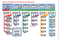
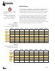
Wiring Color Code Definitions
First Color: Wire
Second Color: Tracer
Example: Red/Orange = Red Wire with Orange Tracer
TracVision G4 will suffer serious
damage if connected to power in
excess of 16 VDC. Complete details
regarding connecting TracVision G4
to ship's power have been provided in
"Connecting
the ADCU to Vessel Power" on page 37.
Gyro Power
Ground
Gyro RXD+
Gyro RXD-
Gyro TXD-
Gyro TXD+
Not Used
IRD Ground Wire
(to IRD)
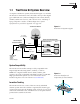
TracVision G4 can either receive power
through the ADCU (as illustrated in
the diagram) or directly from ship’s
power if that is more convenient.
Refer to
"Alternate Method of Providing Power to
the Antenna" on page 32
for details.
TracVision
®
G4 Wiring Quick Reference Guide