Owner's Manual and Instructions GUARDIAN ® Agricultural Animal Confinement Building Heaters with Smart Sense™ Automatic Variable Rate Heat For Use with SmartBox™ Controller MODELS AW250 OUTPUT (Btuh) 250,000 FUEL Propane-Vapor Withdrawal or Natural Gas Patent Pending Congratulations! You have purchased the finest agricultural building heater available. Your new L.B. White heater incorporates the benefits from the most experienced manufacturer of heating products using state-of-the-art technology.
GENERAL HAZARD WARNING ■ Failure to comply with the precautions and instructions provided with this heater, can result in: — Death — Serious bodily injury or burns — Property damage or loss from fire or explosion — Asphyxiation due to lack of adequate air supply or carbon monoxide poisoning — Electrical shock ■ Read this Owner’s Manual before installing or using this heater. ■ Only properly-trained service people should repair or install this heater. ■ Save this Owner’s Manual for future use and reference.
Table of Contents SECTION PAGE General Information . . . . . . . . . . . . . . . . . . . . . . . . . . . . . . . . . . . . . . . . . . . . . . . . . . . . . . . . . . . . . . . . . . .3 Heater Specifications . . . . . . . . . . . . . . . . . . . . . . . . . . . . . . . . . . . . . . . . . . . . . . . . . . . . . . . . . . . . . . . . . .4 Basic Operation . . . . . . . . . . . . . . . . . . . . . . . . . . . . . . . . . . . . . . . . . . . . . . . . . . . . . . . . . . . . . . . . . . . . . .
Heater Specifications Model AW250 SPECIFICATIONS Propane Gas Type Fuel Maximum Input (BTUH) Minimum Input (BTUH) 250,000 65,000 Ventilation Air Required to Support Combustion (CFM) Inlet Gas Supply Pressure Acceptable at the MAX. Inlet of the Heater for Purpose of Input MIN. Adjustment (in. W.C.) Burner Manifold Pressure (in.W.C.) MAX. 1,050 13.5 11.0 8.5 10.0 7.5 0.5 MIN. Fuel Consumption Per Hour Natural Gas MAX. MIN. 11.58 lbs. 250 cu.ft 3.01 lbs. 65 cu.
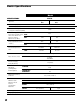
Basic Operation This heater uses Smart Sense™ technology for variable rate heat control. When integrated to a building controller and L.B.White SmartBox™, precise, automated control of the environment is achieved by operating the heater over a broad heat range from 65,000 btu to 250,000 btu. This provides better, more even temperature distribution by allowing the heater to operate where it needs to. This results in consistent temperatures and reduced fuel consumption.
Safety Precautions WARNING Asphyxiation Hazard ■ Do not use this heater for heating human living L.B. White Company to determine combustion air quarters. ventilation requirements of the heater. ■ Do not use in unventilated areas. ■ The flow of combustion and ventilation air must not be obstructed. ■ Lack of proper ventilation air will lead to improper combustion. ■ Proper ventilation air must be provided to support the combustion air requirements of the heater being used.
1. Do not attempt to install, repair, or service this heater or the gas supply line unless you have continuing expert training and knowledge of gas heaters. Qualifications for service and installation of this equipment are as follows: a. To be a qualified gas heater service person, you must have sufficient training and experience to handle all aspects of gas-fired heater installation, service and repair.
Installation Instructions GENERAL WARNING Fire or explosion hazard. Can cause property damage, severe injury or death. 1. Disconnect power supply before wiring to prevent electrical shock or equipment damage. 2. To avoid dangerous accumulation of fuel gas, turn off gas supply at the appliance service valve before starting installation, and perform gas leak test after completion of installation. 3. Do not force the gas control knob. Use only your hand to turn the gas control knob. Never use any tools.
12. A qualified service agency must check for proper operating gas pressure upon installation of the heater. 13. Light according to instructions on heater or within owner's manual. 14. It is extremely important to use the proper size and type of gas supply line to assure proper functioning of the heater. Contact your fuel gas supplier for proper line sizing and installation. 15. This heater can be configured for use with either L.P. gas vapor withdrawal or natural gas.
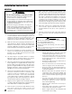
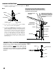
HANGING INSTRUCTIONS 1. Assemble according to the illustration and tighten all eyebolts securely. See Fig. 3. NOTE: REGULATORS SHOULD ALWAYS BE MOUNTED OUTDOORS. IF NOTE: REGULATORSFORCE SHOULDINSTALLING ALWAYS BE MOUNTED OUTDOORS. IFINDOORS, CIRCUMSTANCES THE REGULATOR CIRCUMSTANCES FORCE INSTALLING THE REGULATOR INDOORS, THE REGULATOR’S VENT MUST BE VENTED OUTDOORS USING VENT THE REGULATOR'S VENT MUST BE VENTED OUTDOORS USING VENT LINE NOLINE SMALLER THAN VENT NO SMALLER THAN VENTOPENING. OPENING. FIG.
AIR DIVERTER INSTALLATION INSTRUCTIONS (Accessory) 1. Always use approved pipe thread compound suitable for use with L.P. gas or natural gas on the threaded connections. FIG. 6 VALVE, MANUAL SHUT-OFF 2. Assemble the components together according to the figure. This view is to show general assembly of the components only. The regulator must always be mounted so its vent, regardless of location on the regulator, is always pointed downward. NIPPLE REGULATOR 4.
INTERCONNECTION FOR VARIABLE HEAT ■ Complete installation and operating instructions are provided separately with the SmartBox™ . b. Route the wiring from these leads through the gas inlet hole at the heater’s case. See Fig.9. ■ Use customer supplied wire nuts and other appropriate electrical terminals when interconnecting the SmartBox™ to the heater. c. Attach 1/4 in. insulated female terminals to these wires and connect to either terminal on the valve. See Fig. 9.
Start-Up Instructions Follow steps 1 - 6 on initial start-up after heater installation by a qualified gas heater service person. For normal startup, set the building controller to call for heat. The heater will start. 1. Open all manual fuel supply valves and check for gas leaks using approved leak detectors. 2. Connect the electrical cord to an approved electrical outlet. 3. Set the building controller and L.B.White SmartBox™ to same desired room temperature. 4.
Cleaning Instructions WARNING Fire, Burn, and Explosion Hazard ■ This heater contains electrical and mechanical components in the gas management, safety and airflow systems. ■ Such components may become inoperative or fail due to dust, dirt, wear, aging, or the corrosive atmosphere of an animal confinement building. ■ Periodic cleaning and inspection as well as proper maintenance are essential to avoid serious injury or property damage. 1.
Service Instructions GENERAL WARNING Burn Hazard ■ Heater surfaces are hot for a period of time after the heater has been shut down. ■ Allow the heater to cool before performing service, maintenance, or cleaning. ■ Failure to follow this warning will result in burns causing injury. WARNING Fire and Explosion Hazard ■ Do not disassemble or attempt to repair any heater components or gas train components. ■ All component parts must be replaced if defects are found.
AIR PROVING SWITCH WITH PADDLE 1. Open the case access panel on the control box end of the heater. 2. Remove the two (2) sheet metal screws holding switch with bracket to blower housing. Remove assembly by turning the switch assembly 90°so paddle on the switch arm can be pulled through oblong hole on side of fan housing. FIG. 12 NUTS PADDLE the the the the 3. Disconnect the leads from the air proving switch.
TESTING THE MANUAL RESET HIGH LIMIT SWITCH 5. Allow the switch cool down for about a minute before firmly pressing the reset button on the switch. WARNING Fire Hazard ■ Do not operate the heater with the high limit switch ■ bypassed. Operating the heater a bypass high limit switch may lead to overheating, possibly resulting in a fire, with subsequent damage to the heater, building damage, or loss of livestock.
Gas Pressure Checks WARNING ■ Do not disassemble the gas control valve. ■ Do not attempt to replace any components of the gas 2. Securely connect a pressure gauge to each pressure tap. See Fig.18. FIG. 18 control valve. ■ The gas control valve must be replaced if any physical damage occurs to the control valve assembly. ■ Failure to follow this warning will result in fire or explosions, leading to injury or death to humans, and property damage.
Troubleshooting Instructions READ THIS ENTIRE SECTION BEFORE BEGINNING TO TROUBLESHOOT PROBLEMS. WARNING Electrical Shock and Burn Hazard ■ Troubleshooting this system may require operating the unit with line voltage present and gas on. Use extreme caution when working on the heater. ■ Failure to follow this warning may result in property damage, personal injury or death. The troubleshooting flow charts on the following pages provide systematic procedures for isolating equipment problems.
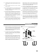
HOT SURFACE IGNITION OPERATION SEQUENCE: — A call for heat occurs from the building’s environment control. — 1-15 VDC is sent from the SmartBox™ variable rate heat controller to the variable rate solenoid on gas control valve. — Line voltage is sent to transformer and to ignition control. — 24 V.A.C. is sent from transformer to the ignition control.
Red LED not on during a call for heat. Problem Heater does not cycle from minimum heat output. Problem Replace transformer No Are 24 volts supplied from transformer? Connect it to the power supply. No Yes No Are 24 volts supplied to ignition module? Yes Yes Yes Yes Set controller to call for heat. No Is building controller Yes calling for heat? Check electrical connections and power supply to transformer. Repair as necessary.
Is airproving switch shorted? (Perform continuity check on airproving switch.) No Is air-proving switch arm or paddle binding on housing? Is there an obstruction in heater outlet? Yes Yes Replace air-proving switch Repair and/or remove obstructions. check for damaged fan housing. Clean or repair as needed. Heater has attempted two ignition trials. Heater is in a 15 minute wait period before attempting its third (final) trial for ignition.
Air proving switch contacts do not close during a call for heat. Two Times Yes No Are 24 volts sent to air proving switch? Yes Defective motor or capacitor. Check wiring between ignition control module terminal PSI and and air proving switch. Repair or replace as necessary. If wiring is good replace ignition control. Yes If Improper voltage is supplied, contact electrician. - OR If no voltage is supplied to motor, check wiring, or replace ignition control module.
Remove components and blow out with compressed air or clean with a soft brush. No Yes Yes Connect igniter to igniter power supply wiring. No Is igniter properly connected? No No Is proper gas Yes pressure supplied to heater? Are 115 volts supplied from ignition control module to igniter? Yes Yes Clean flame sensor with emery cloth or steel wool. No Is flame sensor clean? Defective igniter. Perform ohm check and replace igniter If necessary. Check wiring, repair or replace as needed.
See flame sensor related problems in “Three Time” flash pattern. The heater will continue to operate as normal. This flash pattern identifies that flame sense current is low and that flame failure or improper operation can occur at any time. Five Times Rapid On/Off Cycling of the Burner.
Electrical Connection and Ladder Diagram CAUTION-REFER TO HEATER'S ELECTRICAL CONNECTION DIAGRAM WHEN SERVICING THE HEATER'S ELECTRICAL COMPONENTS TO AVOID WIRING ERRORS & EQUIPMENT MALFUNCTION.
Heater Component Function Air Proving Switch Safety device used to insure that the proper air flow is being achieved before the gas valve is opened. Burner Cast iron component used to channel gas and provide an area at which the fuel may ignite. Burner Orifice Brass metering device used to feed gas to burner at a specific rate. Fan Housing Chamber used for compressing air for ef ficient air movement.
Parts Identification PARTS SCHEMATIC 28
Parts Identification PARTS LIST Item 1 2 3 4 5 6 7 Description Valve, manual shut off with nipple Regulator, Propane Gas, Second stage, vent over outlet Regulator,Propane, Second stage, vent over side Regulator, Natural Gas, Second stage Hose, 1/2 in. ID x 10 ft.
Warranty Policy HEATER L.B. White Co., Inc. warrants that the component parts of its heater are free from defects in material and workmanship, when properly installed, operated, and maintained in accordance with the Installation and Maintenance Instructions, safety guides and labels contained with each unit. If, within 12 months from the date of purchase by the end user, any component is found to be defective, L.B. White Co., Inc.