
Owner manual


MS424 10
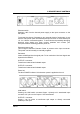
5. DESCRIPTION OF CONTROLS
Phantom switch
Switches +48V from the internal power supply to the Input connector on the
rear panel.
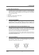
To prevent the chance of damage to any external pieces of equipment, do not
use the +48V power option with unbalanced input sources i.e. those where pins
1 & 3 or 1&2 are connected together. To avoid loud and potentially damaging
electrical noise always turn down monitor speakers and connect your
microphone before switching phantom power on.
Phantom presence led
This led lights whenever Phantom Power is present at the Input connector.
This power can be internally or externally supplied.
Pad switch
Inserts a 20dB pad into the signal path. To be used when Line level signals are
inputted to the MS424.
OUTPUT 3 connector
Transformer balanced and isolated output.
OUTPUT 4 connector
Transformer balanced and isolated output.
Power led
The blue POWER indicator is lit whenever power is applied to the unit.
LINK switch
Pressing the LINK switch connects Output 1 directly to it's associated Input
connector. All 3 pins on the Output 1 XLR are affected.
OUTPUT 1 connector
Output 1 can be either a transformer split output or directly connected
(LINKed) to the Input.