
Owner manual


MS424 11
OUTPUT 2 connector
Transformer balanced and isolated output.
6. OPTIONS
6.1 CONFIGURATION
Each channel of the MS424 consists an input stage and an output stage.
These are connected internally by jumper links which allow the MS424 to be
configured for the following options -
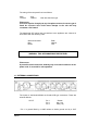
Option Configuration Channels
1 1 IN 4 OUT 4
2 1 IN 8 OUT 2
3 1 IN 12 OUT* 1
4 1 IN 16 OUT 1
* Channel 4 still available as 1 x 4
There are a pair of jumpers associated with each channel and two associated
with the internal buss.
6.2 CHANNEL JUMPERS
CHANNEL JUMPERS
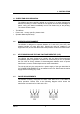
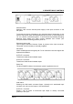
The pair of jumpers for each channel select the channel to be Normal, Master
or Slave. The 3 jumper configurations are shown below.
Normal Master Slave
JP101& JP102, JP201 & JP202, JP301 & JP302, JP401 & JP402
Channel select jumpers as viewed from the front of the unit.
The function of these jumpers can be best understood by refering to the block
diagram on the following page -
NORMAL