
Owner manual


MS424 13
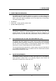
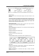
Block diagram of the MS424 showing the channel and bus option jumpers.
Channel Input to Output 1 LINK switching not shown - see diagram on
following page.
Only one Input stage at a time should be connected to the Internal Bus (Master
mode)
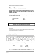
6.3 INTERNAL BUS JUMPERS
There are also two jumpers associated with the Internal Bus and determine the
number of split outputs available.
+48V
Mic
Pad
Input stage
Output stage
1
1
2
3
4
Channel
jumpers
LINK
switch
Internal
bus
Block diagram of a MS424 channel showing LINK switch for Output 1.
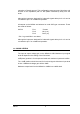
The two bus jumpers allow the MS424 to be configured for 2 x 8, 1 x 12 (with 1
x 4) and 1 x 16 outputs.
812 12 16
JP203
BUS 8/12
JP303
BUS 12/16
Bus option jumpers as viewed from the front of the unit.