
Owner manual


MS424 8
capacitor to Chassis ground. This configuration prevents ground loop hum and
ensures a low impedance path for RF (Radio Interference) away from the
audio.
Although the inputs are designed for 'balanced' signals either pin 2 or 3 can be
connected to pin 1 for unbalanced operation.
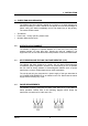
All outputs on the MS424 are balanced on male XLR type connectors. These
are wired as follows -
XLR-M Pin 1 * Screen
Pin 2 Hot (+ve)
Pin 3 Cold (-ve)
* Pin 1 is ground lifted - see above.
Although the inputs are designed for 'balanced' signals either pin 2 or 3 can be
connected to pin 1 for unbalanced operation.
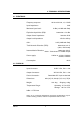
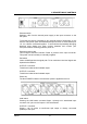
3.6 SIGNAL LEVELS
The input to output voltage gain on the MS424 is 0dB. Maximum input signal
level will depend on the setting of the Pad switch.
0dB (down) position is for microphone levels and maximum input level is 0dBu.
The -20dB position should be used for line level signals. Maximum input level
is then +20dBu and voltage gain will be -20dB.
Maximum output level from the MS424 is +20dBu into a 600Ω load.