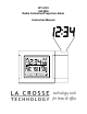
WT-5120 433 MHz Radio Controlled Projection Alarm Instruction Manual
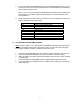
TABLE OF CONTENTS Topic Inventory of Contents/ Additional Equipment About WWVB Quick Set-Up Guide Page 3 3 4 Detailed Set-Up Guide Battery Installation Program Mode Programming Sequence Function Buttons Manual Time Setting Time Zone Setting Daylight Saving Time (DST) Setting 6 6 6 6-7 7 Features & Operations Features Radio-Controlled Time Projection EL Backlight Indoor Temperature Indoor Humidity Remote Temperature Time Alarm Changing Display Mode Mounting Maintenance & Care Troubleshooting Specificatio
INVENTORY OF CONTENTS 1) WT-5120 Alarm Clock 2) TX6U Remote temperature sensor 3) AC adapter/transformer 4) Instruction manual and warranty card. ADDITIONAL EQUIPMENT (not included) 1) Two fresh 1.5V AA batteries (optional for projection alarm clock) 2) Two fresh 1.5V AA batteries (for remote temperature sensor) FEATURES OF PROJECTION ALARM Operation of these features is in section III 1. 2. 3. 4. 5. 6. 7.
QUICK SET-UP GUIDE Hint: Use good quality Alkaline Batteries and avoid rechargeable batteries. 1. Have the projection alarm and remote temperature sensor 3 to 5 apart. 2. Batteries should be out of both units for 10 minutes. 3. Place the batteries into the remote temperature sensor first then into the projection alarm. 4. DO NOT PRESS ANY BUTTONS FOR 15 MINUTES.
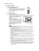
DETAILED SET-UP GUIDE II. BATTERY INSTALLATION A. B. REMOTE TEMPERATURE SENSOR 1. Remove the battery cover. 2. Observing the correct polarity, install 2 AA batteries. The batteries will fit tightly (to avoid start-up problems make sure that they do not spring free during installation). 3. Replace the battery cover. Battery Cover PROJECTION ALARM 1. Remove the battery cover. 2. Observe the correct polarity, and install 2 AA batteries. 3.
III. PROGRAM MODE To enter the Program Mode hold down the “MODE/MIN” button for 3 seconds, until the time flashes in the top of the display. The Program Mode Guide is laid out in a manner that allows you to program each function separately, or you can follow the instructions entirely to program the projection alarm. Complete programming is usually done for the initial set-up, and will require you to skip step 1 and 2 of programming sections D and E.
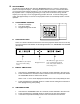
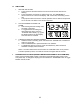
4. Press and release the “MODE/MIN” button to select the appropriate time zone. There are 24 time zones to choose from (based relative to the international time standard of GMT (“Greenwich Mean Time). NOTE: The U.S. time zones will show abbreviations as opposed to the numerical time zone indicator. For example Eastern Time will display “ET” when the Eastern Time Zone is selected 5.
IV. FEATURES & OPERATIONS A. FEATURES 1. 2. 3. 4. 5. 6. 7. Radio-controlled time Projection of time and/or remote temperature LED backlight Display of indoor temperature/humidity or alarm time Indoor temperature and humidity Remote outdoor temperature Time alarm B. RADIO-CONTROLLED TIME 1. The projection alarm will automatically search for the time signal upon initial set-up and every night. 2. When the signal is being received, there will be a “tower” icon flashing to the left of the time display. 3.
D. EL BACKLIGHT 1. 2. E. INDOOR TEMPERATURE 1. 2. 3. 4. F. The projection alarm measures indoor temperature with an internal sensor. This temperature is displayed in °F. The indoor temperature will take time to adjust to the surrounding temperature as the sensor is inside the case. If the remote temperature is placed next to the projection alarm, more often than not the temperature will not be exact with one another. This is not a defect, but simply reflects the difference in measuring methods.
H. TIME ALARM 1. SETTING THE ALARM a. Press and hold “AL/HOUR” button for three seconds until the alarm time is flashing. b. Press and release “AL/HOUR” to advance the hour, and “MODE/MIN” to advance the minute. The time will display “PM” if set to PM, and nothing if set to AM. c. The projection alarm will revert to normal operation when no buttons are pressed for 15 seconds. The alarm is now set and activated. 2. ACTIVATING/DEACTIVATING THE ALARM a.
V. MOUNTING THE REMOTE TEMPERATURE SENSOR The remote temperature sensor can be mounted in two ways: 1) Using screws 2) Using the adhesive tape. A. MOUNTING WITH SCREWS 1. 2. 3. 4. 5. B. MOUNTING WITH ADHESIVE TAPE 1. 2. VI. Remove the mounting bracket from the remote temperature sensor. The bracket should snap off easily. Place the mounting bracket over the desired location. Through the three screw holes of the bracket, mark the mounting surface with a pencil.
TROUBLESHOOTING Problem: Solution: Problem: Solution: Problem: Solution: Problem: Solution: Problem: Solution: Problem: Solution: Problem: Solution: The Projection is faint 1) Use AC adapter 2) Darken surroundings 3) Use fresh batteries (if AC is not used) The LCD is faint. Replace the batteries. “OFL” appears in the indoor temperature LCD. 1) Move unit to an area with warmer or cooler surrounding temperature. 2) Current surrounding temperatures are outside measuring range. No reception of WWVB signal.
SPECIFICATIONS FOR WT-5120 Temperature: Measuring range: Checking intervals: Humidity: Measuring range: Checking intervals: Power source: AC Adapter (included) 14°F to 99°F with 0.2°F resolution (indoor) -21.8°F to 156.2°F with 0.2°F resolution (outdoor) Every 10 seconds indoor, 2 times in 10 minutes for remote temperature. 1 – 99 % Every 10 seconds Input: 120VAC/60Hz Output: DC 3.2V/100MA Battery type: Projection Alarm: 2 x AA, 1.5V (Alkaline) (optional) Sensor: 2 x AA, 1.
WARRANTY INFORMATION La Crosse Technology, Ltd provides a 1-year limited warranty on this product against manufacturing defects in materials and workmanship. This limited warranty begins on the original date of purchase, is valid only on products purchased and used in North America and only to the original purchaser of this product. To receive warranty service, the purchaser must contact La Crosse Technology, Ltd for problem determination and service procedures.
For warranty work, technical support, or information contact: La Crosse Technology, Ltd 2809 Losey Blvd S. La Crosse, WI 54601 Phone: 608.782.1610 Fax: 608.796.1020 e-mail: support@lacrossetechnology.com (warranty work) sales@lacrossetechnology.com (information on other products) web: www.lacrossetechnology.com All rights reserved.