User’s Manual Guardian™ Jr. Airflow Monitor 1. Applies primarily to older Models 4865000, 4865001 2. Some operation and troubleshooting information applies for newer 97432-xx Series 3. See separate Instruction Sheets for installation on newer 97432-xx Series To receive important product updates, complete your product registration card online at register.labconco.com Labconco Corporation 8811 Prospect Avenue Kansas City, MO 64132-2696 800-821-5525, 816-333-8811 FAX 816-363-0130 E-MAIL labconco@labconco.
Copyright © 2000, 2007 Labconco Corporation. All rights reserved. The information contained in this manual and the accompanying products are copyrighted and all rights reserved by Labconco Corporation. Labconco Corporation reserves the right to make periodic design changes without obligation to notify any person or entity of such change. Warranty Labconco provides a warranty on all parts and factory workmanship.
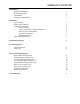
TABLE OF CONTENTS Introduction Components Shipped General Description Performance Component Identification 1 2 2 3 Installation Alarm Module Power Supply Module Electrical Connections Protector Hoods 8 Foot, 230V Hoods with External Blower Basic 47 and 70 Fume Hoods Perchloric Acid Hoods Radioisotope Hoods Initial Adjustment Setup 4 4 5 5 6 6 6 7 7 Installation Drawings 9 Normal Operations Alarm Activation Alarm Test 11 11 Electrical Wiring Diagrams Remote Blower Hoods 115V 8' Remote Blower Hoods 11
PREFACE Thank you for displaying confidence in us by selecting a Labconco Guardian Jr. Airflow Monitor. Our design engineers, assemblers and inspectors have utilized their skills and years of experience to ensure that the new Guardian Jr. Airflow Monitor meets our high standards of quality and performance. IMPORTANT NOTICE This manual should be read carefully by all the end users in order to become familiar with the operation of the Guardian Jr. Airflow Monitor.
INTRODUCTION Components Shipped Carefully check the contents of this package for damage that may have occurred in transit. Do not discard the carton or packing material until all components have been checked against the following component list and the equipment has been installed and tested. As shipped, the carton should contain the following: Model 4865000 – Guardian Jr.
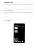
INTRODUCTION General Description The Guardian Jr. Airflow Monitor is designed to continuously monitor airflow through fume hoods. This permanently installed device provides both visual and audible alarms to alert the user of abnormal airflow conditions. A green light on the front of the monitor indicates normal flow conditions. When flow conditions lower than the set point are encountered, a red light is activated along with an audible alarm.
INTRODUCTION Component Identification 1. Air Inlet A portion of the air coming into the hood passes through the air inlet and across the flow sensors. 2. Normal Flow Indicator This green light indicates normal flow conditions. 3. Alarm Indicator This red light is activated approximately 6 seconds after the low flow set point is reached. 4. Test/Reset Button If no alarm is present, this button will cause the red lamp to light and the audible alarm to sound.
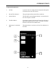
INSTALLATION Disconnect your fume hood from its electrical service prior to beginning the installation of your new monitor. The installation of your monitor is separated into two segments, the alarm module and the power supply assembly. Installation is as follows: Alarm Module 1. Remove the right hand corner cover panel from your Protector Fume Hood. This is achieved by removing the service fixture knobs, if provided, and then removing the three Phillips head screws retained in the corner cover.
INSTALLATION 10. Insert the velocity probe into the open end of the vinyl tubing and position the probe in the 3/8" diameter hole drilled in Step 9. Place the end of the airflow hose with the nozzle inside the hose near the exhaust duct as the nozzle helps regulate airflow properly. RTV the probe in position to complete your installation. 11. Locate caution label directly above the alarm on the appropriate corner cover. Electrical Connections 12.
INSTALLATION 8 Foot, 230 Volt Hoods with External Blower 230 Volt: Locate the blue wire, which is connected to the blower switch. Disconnect this blue wire from the blower switch terminal and connect to the blue wire in wiring harness #48611 using the attached terminal. Reconnect the remaining terminal of the blue wire (part #48611) to the original blower switch terminal. Locate the brown wire on the blower switch, which is adjacent to the blue wire just connected above.
INSTALLATION terminal on the white wire wiring harness #48610 by removing the terminal, stripping the wire and installing a wire nut. Locate the yellow wire on the hood blower switch. Remove the yellow wire from the blower switch and connect the black wire #48615 to the blower switch terminal where the yellow wire was located.
INSTALLATION increments, at intervals about 10 seconds apart to allow for delayed reaction of the alarm itself. 7. Readjust the fume hood airflow to its normal levels. 8. Note: If the low airflow volume cannot be adjusted, then a 1/4 to 1/3 of a turn counterclockwise can be adjusted to set the airflow volume alarm condition at 20-25% below normal operating levels.
INSTALLATION DRAWINGS 9
INSTALLATION DRAWINGS 10
NORMAL OPERATIONS Alarm Activation The audio and visual alarm will activate approximately six seconds after an alarm condition is detected. To temporarily mute the audible alarm, press and release the test/reset button. NOTE: After an alarm condition has been detected, the red light will stay on. The audible alarm will remain muted until airflow returns to normal levels. Alarm Test When no alarm is present, the alarm can be tested by pressing the test/reset button.
ELECTRICAL WIRING DIAGRAMS 12
ELECTRICAL WIRING DIAGRAMS 13
ELECTRICAL WIRING DIAGRAMS 14
ELECTRICAL WIRING DIAGRAMS 15
ELECTRICAL WIRING DIAGRAMS 16
ELECTRICAL WIRING DIAGRAMS 17
ELECTRICAL WIRING DIAGRAMS 18
ELECTRICAL WIRING DIAGRAMS 19
ELECTRICAL WIRING DIAGRAMS 20
TROUBLESHOOTING Symptom Suggested Recommendations No Lights Power supply not plugged into proper voltage; plug in power supply. Monitor rear connection is disconnected; verify that the connector is correctly installed. No Audible Alarm Alarm has been silenced using test/reset button. Wrong Alarm Set Point Potentiometer was not properly adjusted. Repeat calibration steps outlined in this manual. Continuous Alarm Blower speed has changed.