
Owner's manual
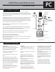


LAKOS PC SCreen Installation Guide
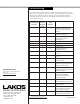
Flow Rates & Pressures
Item
#
Description
1 Screen outlet pipe assembly
2 Band clamp
3 E.P.D.M. rubber seal
4 Plastic ring
5 Axle pipe
6 Spider bushing cap assembly
7 Frame & drive vane assembly
8 Screen cover & rivet pack for frame
9 Jet pipe assembly
10 Delrin spindle
11 Bushing & end cap assembly
12 Spindle nut & washer
13 Hub cap
14 #10 stainless steel 5/8-inch screw
for end caps & hub cap (package
contains up to 64 scerws)
15 Backwash spray nozzles (1 to 6x)
16 Drive nozzle
17 Spider bushing
18 Lid bushing
MODEL
PC 915
PC 1415
PC 924
PC 1424
PC 1924
PC 2424
PC 2924
PC 3424
U.S. gpm
350
560
650
1000
1350
1700
2050
2400
m3/hr
80
130
150
230
305
385
465
545
U.S. gpm
250
400
450
700
950
1200
1450
1700
m3/hr
60
90
105
160
215
275
330
385
MAXIMUM FLOW RATE
(10 & 18 Mesh) (30 Mesh)
(inches)
1-1/4
1-1/4
1-1/4
1-1/2
1-1/2
1-1/2
2
2
BACKWASH
RETURN LINE
CONNECTION
psi
55-80
60-80
60-100
65-100
70-100
75-100
75-100
75-100
kPa
385-560
420-560
420-705
455-705
490-705
525-705
525-705
525-705
*REQUIRED
BACKWASH
PRESSURE
U.S. gpm
10
15
12
18
25
39
41
50
m3/hr
2.5
3.5
2.5
4.0
5.5
8.0
9.5
11.5
APPROXIMATE
BACKWASH FLOW
AT PROPER PRESSURE
*This pressure required at the PC Screen connection. If pressure is not adequate for e cient backwash operation, a booster pump
may be necessary
Parts Listing
14
13
12
18
11
10
16
15
9
8
7
17
6
5
4
3
2
1
Note: When ordering
replacement parts, please
speci y the complete model
number of your PC Screen
(example: PC-242410GE12) to
facilitiate shipment of a part
compatible with your particular
unit.