INSTRUCTION MANUAL ACTIVATOR 282 BATTERY CHARGER FOR 24 VOLT AIRCRAFT AND MILITARY BATTERIES P/N ACTIVATOR 282 (also called 282-300) Serial numbers 21228 and higher, manufactured January 2009 and later. Issued By: Power Products Inc. / Lamar Technologies LLC 14900 40th Ave. N.E. Marysville, WA 98271 Tel: 360-651-8869 Fax: 360-651-6677 www.power-products.com or www.lamartech.
Table of Contents CHAPTER TITLE FIG. 1 Photo with Callouts 2 FIG. 2 Dimensions 3 0.1 Quick Instructions 4 1.0 Introduction 5 2.0 Charging 6 3.0 General Operation 7 4.0 Battery Charging Protection 8 5.0 Nickel Cadmium Topping 9 6.0 Calibration Verification 9 7.0 Maintenance 15 8.0 Troubleshooting 16 9.0 Specifications 17 Certification of Factory Calibration 18 Warranty 19 1 PAGE NO.
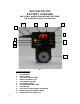
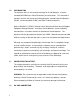
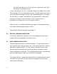
ACTIVATOR 282 BATTERY CHARGER FOR 24 VOLT AIRCRAFT AND MILITARY BATTERIES P/N ACTIVATOR 282 (also called 282-300) 11 8 4 1 . 2 . 9 5 3 6 7 10 0 ITEM NO. DESCRIPTION 1. 2. 3. 4. 5. 6. 7. 8. 9. 10. 11. 2 FIG.
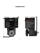
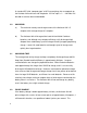
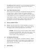
DIMENSIONS 3.5 4.5 5.75 FIG.
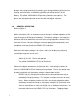
Activator Outline ACTIVATOR 282 BATTERY CHARGER FOR 24 VOLT AIRCRAFT AND MILITARY BATTERIES 0.1 QUICK INSTRUCTIONS CAUTION: Read the complete instructions before use. These quick instructions are for reference only. A. Set switch of ‘Off’: Select Lead Acid or NiCad. B. Plug in AC line, 90-240V 50/60/400 Hz. Connect Activator to battery via Quick-Connect knob. C. Switch to on. Digital Voltmeter reads charge voltage. CHARGING LED on. Voltage begins to rise.
1.0 INTRODUCTION The Activator 282 is a self contained charger for 24 Volt batteries, using the standard MS 3509 Style “Quick Disconnect” pin terminations. This connector is found on most 24 Volt aircraft and military batteries, Sealed Lead Acid Batteries (SLAB), vented Lead Acid (VLRA), and Nickel Cadmium batteries.
A standard IEC-320 “computer type” of AC line cord plugs into a receptacle on the Activator 282 and into a wall receptacle. AC line input is 1-- ~ 240 Volts 50 / 60 /400 Hz and can be used worldwide. 2.0 CHARGING a.) The maximum steady-state charge current of the Activator 282 is 5 amperes with average charge of 3 amperes. b.
protects the charger and brings the battery up to charge efficiently with minimum heating, and also helps in conditioning (breaking chemical barriers) of the battery. The yellow ‘CHARGING LED pulsating indicates these pulses. The pulses are too rapid to be read on the Activator 282 digital voltmeter. 3.0. GENERAL OPERATION Refer to Figure 1. When switched to ‘ON’, an automatic cycle of charge is initiated regardless of the state of charge or discharge of the battery.
will reduce from 30 minutes to 15 minutes for a second cycle, and then to two minutes for subsequent cycles. If, when switched from ‘Off’ to ‘On’, the battery voltage rises rapidly from its Open Circuit Voltage (OCV) to a voltage above 28 volts, this high voltage surge may be due to the battery not accepting charge. With Lead Acid batteries, this indicates that the battery is sulfated. NiCad batteries may also exhibit this under certain conditions of corrosion at the cell linkages.
If the battery heats up on charge to 45°C (113°F) the charge will cut off and the OVERTEMP/FAULT LED will illuminate. When the battery cools down to approximately 90°F, the charge restores. 4.2 FAULT INIDICATION AND CUTOUT While charging with the Activator 282, a 24 Volt battery voltage will continuously rise to over 28 Volts.
Verification of output is the only check that is required on an annual basis. Voltage test points are provided on the unit and verification can be accomplished with a calibrated voltmeter such as the Fluke 77 / AN. If the Activator 282 supplies the correct voltage, the required charge current will automatically follow, and charge amperes are a consequence of the charger and battery voltage.
1) Activator 282 to be verified 2) This requires a battery or resistance load such as a 10 Ω 100 Watt power resistor. A DC ammeter (0 – 10 Amps) can be connected in series with the battery and load to verify amperes if desired. BATTERY LOAD a) Check that the battery on charge reaches 28 Volts (it will continue to increase). Approximately 30 minutes after reaching 28 Volts, the yellow CHARGING LED will go out and the green READY Lamp will illuminate. The battery voltage will drop.
6) (Optional, for use with power resistor) Wire, #22AWG (0.65mm), 6 ft (2 meters) 7) (Optional, for use with power resistor) Wire, #18 AWG (1mm), 6 ft (2 meters) Procedure: 1) (Optional) Into each tip plug connect 3 feet of #18AWG and #22AWG wire. The #22 will go to a voltmeter and the #18 will sometimes be connected to the power resistor. 2) Connect the Activator 282 to a Lead Acid battery and set the front panel switch to “Lead Acid”.
6.5 VERIFYING CHARGING VOLTAGE THRESHOLDS (MIN-MAX METER) This procedure is not required but may be performed as desired. It achieves the same results as the previous procedure, but uses a recording instrument to watch battery voltages instead of a technician. Tools and materials: a) Activator 282 to be verified b) Battery for test c) Calibrated “min-max” holding voltmeter such as the Fluke 287.
7) After at least one additional charge and discharge cycle, read the minimum and maximum voltages observed. The highest voltage must be 28.2V ± 0.3 Volts. The lowest voltage must be 25.2V ± 0.3Volts. If either voltage is outside the listed range, the Activator 282 must be returned to the factory for repair and calibration. 6.6 VERIFYING TOPPING TIME This procedure is not required but may be performed as desired. The timing of the Activator is set by a crystal oscillator, verified at the factory.
d) After 30 ± 3 minutes of topping time the green READY LED will light and the yellow CHARGING light will extinguish. Note the elapsed time. The indicated voltage will drop towards 25.2 Volts over a few seconds (time set by the capacitor and resistor choice). e) As the indicated voltage drops below 25.2 Volts, the yellow CHARGING LED will again light and the green READY LED will extinguish. Immediately begin timing the second topping duration. f) After 15 ± 1.
c) AC Line Cord – If the insulation or plug is damaged, replace the cord. 8.0 TROUBLESHOOTING CAUTION: Do not attempt to repair the electronics – contact Power Products. PROBLEM POSSIBLE CAUSES Voltage on charge goes to maximum The battery is sulfated or connections immediately corroded 1. The battery voltage is low. 2. If the battery voltage does not begin to rise within one hour, the battery is defective.
9.0 SPECIFICATIONS Dimensions: The unit has a T-shaped configuration. Max. Unit width: 4.5” Max. Unit height: 5.75” Max. Unit depth: 3.5” Note: See page 2 for dimensional images Weight: 2 LBS. AC Input: 90 – 240 VAC AC Inlet: Standard IEC-320 (60320) receptacle. 3 wire grounded. 50/60/400 Hz, 500 mA Mates with USA and international IEC line cords. Internal AC fuse protection. AC Line Cord: Provided: 6 ft. 3 Wire with IEC-320 plug one end and standard NEMA 15-5, 125V plug on the other end.
Lamar Technologies LLC 14900 40th Abve. N.E. Marysville, WA 98271 360-651-8869 CERTIFICATION OF FACTORY CALIBRATION BATTERY CHARGER – DIRECT CONNECT MODEL ACTIVATOR 282 ● P/N: 282 APPLICATION: Automatic charging of 24 volt aircraft batteries – vented Lead Acid, sealed Lead Acid or Nickel Cadmium. SPECIFICATIONS: NOTES: ● AC input Nominal 115 or 230VAC 50/60/400Hz – auto ranging ● On/Off Toggle Switch ● Lead Acid / NiCad Slide Switch A. Unit manufactured and calibrated under MIL-I-45208 B.
1 YEAR WARRANTY POWER PRODUCTS INC. warrants its products to be free from defects in workmanship and material for a one-year period from the date of shipment to the distributor, original equipment manufacturer (OEM), or original end user. If any product shall prove to be defective during the warranty period, POWER PRODUCTS INC. will repair or replace such part. There are no warranties, which extend beyond the description on the face hereof.