
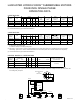
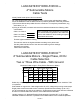
Electrical Schematic


PAGE 11
LANCASTER HYDRO-FORCE™
3-Wire Control Box
Troubleshooting
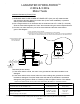
Troubleshooting procedures with POWER ON
WARNING: Fatal electrical shock hazard. Do not touch any live parts.Onlyqualiedpersons
should perform the following procedures.
Measure Voltage…
• With control box lid removed: the motor cannot run because the electrical components on the
lid are removed from the circuit. Measure line voltage by placing a voltmeter across the L1 and
L2 terminals in the control box.
• With control box lid attached: the motor can run because the electrical components on the lid
complete the circuit; voltage cannot be measured from inside the box. Measure line voltage by
placing a voltmeter across the L1 and L2 terminals of the pressure switch. The voltage reading
should remain the same except for a slight drop at startup. Excessive voltage drop could be
causedbylooseconnections,badcontacts,groundfaultsorinsufcientpowersupply.
Control box relay “chatter” is caused by low voltage or ground faults.
Voltage reading should be 230V +6%/-10%.
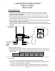
Measure Current (Amps)…
• With control box lid attached: the motor can run because the electrical components on
the lid complete the circuit; current cannot be measured from inside the box. Measuring the
amount of current between the control box and motor is helpful when troubleshooting because
it can indicate the operating conditions of the motor. If the measured motor current exceeds
Service Factor Max Amps (SFA) the motor is running in a possible overload condition. This
could be caused by the pump operating at open discharge or on the far right side of the pump
curve. A bound pump will cause Locked Rotor Amps and overload tripping. If the measured
motor current is much lower than expected the motor is in a possible under-load condition.
This could be caused by the pump running at shut-off (dead-head) pressure, a stripped spline
(motor shaft-pump coupling), a plugged pump intake screen or blocked system piping thereby
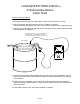
restrictingow.Aclamp-onammetercanbeusedtomeasureampdrawintheyellowlead
(line amps), black lead (main winding amps) and red lead (start winding amps). In some
installations the leads from the control box to the motor will be in conduit or otherwise
difcult to access. If it is possible to measure current in the motor leads…
1. Current in the yellow and black leads will spike at startup and then come down in less than
1 second.
2. Current in the red lead should momentarily be high at startup and then drop within 1
second.Thisveriespropercontrolboxrelayoperation.
Control box relay failure will cause the red lead current to remain high and overload tripping.
Control box start capacitor failure or an open relay is indicated by the red lead current not
momentarily high at startup.
Amp readings should not exceed values listed in the 3-WIRE MOTORS chart on the
OPERATING DATA PAGE.
Refer to Troubleshooting procedures with POWER OFF for control box
component diagnostic testing.