
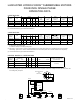
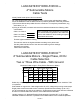
Electrical Schematic


PAGE 12
LANCASTER HYDRO-FORCE™
3-Wire Control Box
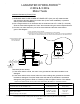
Troubleshooting
Troubleshooting procedures with POWER OFF
Control box component diagnostic testing: CAUTION- Make sure the power is turned off.
Start Capacitor…
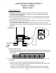
1) Physical Inspection – If the vent (a small rubber diaphragm located at the top end of the start capacitor’s
plastic case) is bulging, or if a foul smell or a buildup of black soot is evident, the start capacitor has vented
due to exposure to over-current, heat or prolonged use. Do not attempt to the run submersible well pump
with a bulging, leaking, or damaged start capacitor. It must be replaced.
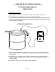
2) Test the Start Capacitor – CAUTION -Therstoperationintestingacapacitoristodischargeit.Holding
a screwdriver by its insulated (plastic or wood) handle and using the screwdriver’s metal shank to make
contact between the capacitor’s terminals will short out the terminals but can also damage the capacitor. To
avoidelectricshockNEVERplacengersacrosstheterminalsbeforeproperlydischargingthecapacitor.
The start capacitor has a bleed resistor soldered across the terminals. The added resistor bleeds off the
charge.
a) Test capacitor using an ohmmeter- capacitors can be roughly checked using an ohmmeter. Disconnect
the wiring from the capacitor terminals but keep the bleed resistor in place. Set the ohmmeter scale
to R x 1000. Connect the ohmmeter test leads to the capacitor terminals. What you are actually doing
is attempting to charge the capacitor using the battery in the ohmmeter (make sure the battery in the
ohmmeter is good).
Good Capacitor:theohmmeterindicatorshouldrstmovetowardszeroandthendriftback,settlingat
the resistor value of approximately 15,000 ohms or 15 on the R x 1000 scale. Note- if the resistor was
removedfromthecapacitorterminals,theindicatorwillrstmovetowardszeroandthenincreaseback
towardsinnity.Iftheresistorisnotdamaged,re-solderitacrossthecapacitorterminals.Otherwise
attach and solder a new 15,000-18,000 ohm, two watt bleed resistor across the terminals.
Note- using an ohmmeter and getting a good capacitor test result as described above only indicates
that the capacitor will hold a charge but not how much charge. The use of a capacitor tester is highly
recommended (see 2b.).
Open Capacitor: the indicator will read high with no dip and no recovery. Replace defective capacitor.
Shorted Capacitor: the indicator moves towards zero and stays at zero. The capacitor has an internal
short and will not take the charge. Replace defective capacitor.
b) Test capacitor using capacitor tester- capacitors can be checked more accurately by using a capacitor
test meter that measures capacitance (the ability of the capacitor to store an electrical charge) in
microfarads (MFD). Most digital multimeters now have scales for testing capacitors. Disconnect the
wiring from the capacitor terminals and cut off the bleed resistor wire from one capacitor terminal (leave
enough wire to re-solder resistor to terminal if capacitor tests good). Push resistor wire away from
capacitor terminal. Set the capacitor tester to the correct MFD scale or if using a digital multimeter set
the meter to the capacitance test function. Connect the meter test leads to the capacitor terminals.
Measured capacitance should be within the MFD range printed on the capacitor. If the meter reads
that the capacitor failed to hold its rating, replace the defective capacitor. For single value MFD ratings,
the rule of thumb is to replace the capacitor if capacitance drops below 10% of the original value. If
printing on the capacitor is unreadable, refer to CONTROL BOXES chart on the OPERATING
DATA PAGE for MFD values.