
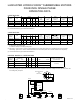
Electrical Schematic


PAGE 13
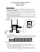
Start Relay (a.k.a. Potential or Voltage Relay)…
1) Physical Inspection – A faint click from inside the control box can be heard very shortly after the
submersible pump motor starts, i.e. the relay contacts should be closed during the initial starting cycle,
but should open (faint click) as the motor comes up to speed. If the relay “chatters”, i.e. clicks quickly
and repeatedly, the supply voltage could be low. The start relay is designed to operate ONLY on 230-volt
systems. If the submersible pump attempts to start, but is unable to do so or if there is a humming sound,
check the relay to see if the contacts are damaged or its coil opened.
Note - Sticking relay contacts (contacts that will not open as described previously) could be damaged from
a defective start capacitor bleed resistor.
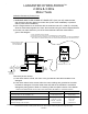
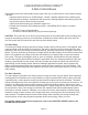
2) Test the Start Relay – Disconnect wiring from the start relay.
a) Test the relay coil using an ohmmeter- Set the ohmmeter scale to R x 1000. Connect the ohmmeter test
leads to #2 & #5 on the relay.
Coil resistance correct reading: 4.5 – 7.0 (4,500 to 7,000 ohms).
b) Test the relay contact using an ohmmeter- Set the ohmmeter scale to R x 1. Connect the ohmmeter test
leads to #1 & #2 on the relay.
Contact resistance correct reading: Zero.
Note- relay contacts are normally closed and measured resistance should be zero (0 ohms). Higher
resistance readings indicate deterioration of the contacts.
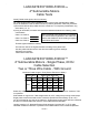
Control Box Wiring Diagram
230 V - 60 HZ
AUGUST 2014
1/2, 3/4 & 1 HP
1
2 5
B (MAIN) Y R(START) L2 L1
MOTOR LEADS LINE LEADS
GND
GREEN
GND
GREEN
RELAY
START CAPACITOR
with
bleed-resistor
BLACK
BLACK
YELLOWYELLOW
RED
ORANGE