
User's Manual


2: Installation
Prior to installation, refer to the following lists to ensure that you have all the items
shipped with the unit as well as all other items required for proper installation.
Standard Accessories
Mounting bracket hardware:
Vertical (SLP-V, SLPY* models) – two removable flanges with four M4 screws
and two mounting L-brackets with two nut plates and four sets of screws and
washers
Horizontal/Rack (SLP-H, SLPX* models) – two mounting brackets and four
screws
RJ45 to RJ45 serial rollover cable
RJ45 to DB9F serial port adapter (for connection to standard DB9M DTE serial
port)
Outlet retention clips, one per outlet (208-240V units only)
Power input retention bracket hardware
Two removable T-brackets with two 40mm screws
Additional required Items:
Phillip screwdriver
Screws, washers and nuts to attach the SLP to your rack
Power input cord (purchased separately)
*SLPY, SLPX includes RJ12 link cable
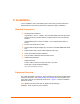
Equipment Overview
The outlets are labeled 1 through 16. These numbers may be used in commands that
require an outlet name. See
Outlet Naming and Grouping for more information. The
power inlet connects to the electrical power source.
Figure 2-1 shows the hardware
features of the SLP.
Note: Models SLP-H8 and SLP-V16 are displayed in the following
illustration. Other models may have variations.
SecureLinx SLP Remote Power Manager 9