
Installation & Assembly

WARNING! SHUT POWER OFF AT FUSE OR CIRCUIT BREAKER .
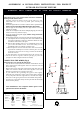
ASSEMBLING THE FIXTURE (Fig.1).
*Shut off the power at the circuit breaker and remove old fixture,
including the old small hardware.
1. Carefully unpac
k
new fixture and lay all the
p
arts on a clea
r
surface.Take care not to lose any small parts necessary for
installation.
2. Install the ligh
t
b
ulbs in accordance with the fixture specifications
NOTE: DO NOT EXCEED THE SPECIFIED WATTAGE!
3. Threa
d
nipple of the finial(A) into cove
r
(B) an
d
loc
k
i
t
securely
with the hex nut(D).
4. Attach the cover(B) onto the fixture
b
ody(E) aligning the holes on
it and lock it securely with hex nut(C).
5. Screw the
p
ole(F),(G) togethe
r
tightly. Follow wiring instructions
carefully (see fig.2).
6. Pu
t
the
p
ole(I) onto the concrete
b
ase using the mounting knob(J).
A. The depth of th e
b
ase will depend on local soil conditions and
frost line.The diamete r of the base should be 305mm in order
to hold the anchor bolts on the plate.
B. Take the th r e e bo l t s ( L ) and run a hex nut(M) fully do w n each
part of the threaded section. Insert the bolt(L) to the
template(K) and secure with the second hex nuts.
C. Mix and pour the concrete into the former until it reaches the
top.Push the assembly into concrete until the plate are 0.25
inches above the concrete .Leaving 2.5 inches of the thread
above the concrete.
D. It is important to level the template before the concrete sets.
7. Install the fixture together with the
p
ole(F),(G) onto the
pole(I),secure them using the machine screws(H).
CONNECTING THE WIRES (Fig.2)
*Feed the fixture wires through the pole(F),(G) .
1. Take the black wire(hot) from the outlet box and the black wire of
fixture and twist bare ends together. Twist wire connector onto end
of wire until snug.
2. Repeat same process with white wire(neutral) from outlet box and
white wire of fixture. NOTE: Twist wires together in the same
direction you twist the wire connector onto wires.
3. If your outlet box has a grounding wire (green or bare copper),
attach this wire and the bare copper wire from the fixture together
as step 1.If junction box has no ground wire, attach the bare copper
fixture wire to the green ground screw in the bottom of the pole(I).
4. Tuck the wire connections neatly into the pole.Take the fixture(E)
mount onto the pole(F) .
Your installation is now complete. Return power to the
junction box and test the fixture.
Fig.1
Fig.2
White or
HOUSE
Black
WIRES
(Hot)
Smooth
FIXTURE
WIRES
Black or
Ribbed
WIRES
FIXTURE
Bare Copper(Ground)
FIXTURE
WIRES
Copper
(Ground)
HOUSE
(Neutral)
WIRES
White
Bare
Green or
WIRES
HOUSE
Listed
U
L
R
ASSEMBLING & INSTALLATION INSTRUCTIONS FOR PRODUCT
OUTDOOR POST LIGHT FIXTURE