
Installation Guide

Standard Acrylic Units
Installation Instructions
altered threshold heights do not have wooden bottoms to
reinforce the oors. By placing the unit on some type of
block, the drain will not rest on the oor. The will allow
the draft of the oor to be maintained without the weight
of the shower unit pushing the drain upward. The block
should only be placed at the outside corner edges of the
unit and should not be placed under the middle of the
threshold. This procedure should only be used during
storage and not during installation. Some units may ship
with a template under them. This template should stay in
place until the unit is to be installed.
Installation Procedure - .75” Threshold
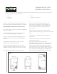
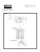
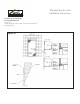
1. At the time of installation, prepare the installation
area in which the unit will sit by pouring a multipurpose
thin set bed of which the pit walls become the boundary.
Place the unit onto the mix and make sure the tub sits
plumb and ush. This procedure will eliminate any voids
under the tub. Too much mix can cause the oor to push
upward during the cure an violate the drainage of the
unit as well as bow the threshold of the unit (see Figures
2 & 4).
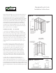
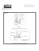
2. In order to ensure proper draining of the unit, you
must: a) Core drill a diameter of 10” and a depth of
.5” on a concrete surface that is “pre-fabbed” around
the drain pipe; or b) Box out a diameter of 10” and
a depth of .5” in the poured slab around the drain
pipe. Following these instructions will allow the oor
surface of the unit to maintain its draft and allow the
unit to drain properly (see Figure 5). This is absolutely
necessary to allow for the depth of the drain pull that
may go below the bottom of the threshold of the unit.
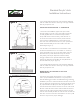
3. A unit with .75” barrier free threshold may be
recessed or the outside oor may be built up .25” in
order to allow the nished oor to come with in .5” of
the top of the threshold on any 60” barrier free (ADA) unit.
The pit depression should be deep enough to allow for the
specied nished oor. Detail and the pit dimensions should
allow for the placement of the unit inside the pit (see Figure
6).
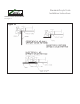
Acrylic Bathing Units
Installation Instructions
block, the drain will not rest on the floor. The will allow
the draft of the floor to be maintained without the weight
of the shower unit pushing the drain upward. The block
should only be placed at the outside corner edges of the
unit and should not be placed under the middle of the
threshold. This procedure should only be used during
storage and not during installation. Some units may ship
with a template under them. This template should stay in
place until the unit is to be installed.
SHIM INFORMATION
Each manufactured unit is made with the intent of being
shimmed upon installation. This allows the job site to
compensate for nay settling or slop that could occur
at the site floor. The shim should be placed under the
unit after it is put into place and is being leveled. An
adhesive should be applied to the bottom of the shim
to permanently secure it in place when shimming on
concrete. When shimming on wooden floors, nail the
shim in place to prevent movement. A minimum of two
shims should be used on each unit to ensure proper
support and a solid base.
INSTALLATION PROCEDURE- .75” Threshold
1. At the time of installation, prepare the installation
area in which the unit will sit by pouring a multipurpose
thin set bed of which the pit walls become the boundary.
Place the unit onto the mix and make sure the tub sits
plumb and flush. This procedure will eliminate any voids
under the tub. Too much mix can cause the floor to push
upward during the cure an violate the drainage of the
unit as well as bow the threshold of the unit (see Figures
2 & 4).
2. In order to ensure proper draining of the unit, you
must: a) Core drill a diameter of 10” and a depth of
.5” on a concrete surface that is “prefabbed” around
the drain pipe; or b) Box out a diameter of 10” and
a depth of .5” in the poured slab around the drain
pipe. Following these instructions will allow the floor
surface of the unit to maintain its draft and allow the
unit to drain properly (see Figure 5). This is absolutely
necessary to allow for the depth of the drain pull that
may go below the bottom of the threshold of the unit.
3. A unit with .75” barrier free threshold may be
recessed or the outside floor may be built up .25” in
order to allow the finished floor to come with in .5” of
the top of the threshold on any 60” barrier free (ADA)
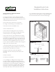
Figure 2
Figure 3