LAVA HQ-ST Link System Manual Rev.
Table of Contents Introduction System Design Theory of Operation of the LAVA HQ-ST Link Primary Hardware Components of the HQ-ST System ST Plus HQ Plus Secondary Hardware Components of the HQ-ST System HQ Remote Console HQ Remote Poller Software Components of the HQ-ST Link System HQ Basic Software ST Plus Configuration Console LAVA Ether Link Manager Utility LAVA HQ Plus Install Equipment Needed General METHOD #1: Headquarters Installation using HQ-Basic (recommended method) METHOD#2: Headquarters Installa
Introduction System Design The LAVA HQ-ST Link consists of ST Plus devices installed at each store. The ST Plus devices communicate with an assigned and dedicated HQ-Plus device at the head office. The ST Plus devices are attached to the cash register(s) in each store, and to the store's Internet connection. Polling software running on a head office computer can poll each cash register, via the HQ Plus.
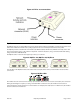
Primary Hardware Components of the HQ-ST System The ST Plus and HQ Plus are the two essential hardware components in an HQ-ST Link. ST Plus devices, attached to ECRs in stores, connect to their assigned HQ Plus device located at a head office. ST Plus The ST Plus is a device operates as a TCP/IP Raw Client, with the intention of providing a store-side serial-to-Ethernet interface to an ECR or other similar device.
Figure 4: ST Plus: rear connections HQ Plus The HQ Plus operates as a TCP/IP Raw Server, with a known IP:Port address. The HQ Plus is intended to provide a headoffice serial-to-Etherenet interface for a polling application to access remotely located device to be polled.
Secondary Hardware Components of the HQ-ST System The HQ Remote Console and HQ Remote Poller provide the capability to locate a parallel "HQ site" which can be readily re-located. The HQ Remote Console and the HQ Remote Poller can be deployed as standalone devices, at the same or at separate sites. Enabling and disabling of the remote devices is controlled from the main HQ Plus through the HQ Basic software control to allow or disallow remote console and remote poller functions accesses.
Software Components of the HQ-ST Link System While not essential to the main task of polling over IP, the following components supplement the basic HQ-ST Link and and assist installation or are required for device configuration . HQ Basic Software This system management utility, supplied with HQ Plus hardware, provides configuration interfaces for HQ Plus and ST Plus devices, and presents a tabular view of the state of all ST Plus connections current on a given HQ Plus.
LAVA HQ Plus Install Equipment Needed To set up an HQ Plus for polling you will need: • polling software [not supplied] • LAVA HQ Basic software (See “HQ Basic: Operation” on page 19.
4. Once connected, double-click on the last entry in the table (the entry is named “CONSOLE LOCAL” and denotes the HQ Plus that is currently connected). 5. In the Network Settings screen that appears, enter at least the following: the IP address of this HQ Plus (factory default is 192.168.0.35) and an Identification Key matching that used by ST Plus units targeting this HQ Plus (factory default is a string of zeros).
6. The default values in the Serial Settings tab are for display only and cannot be changed. 7. The serial settings in the “Modem Settings” tab must be set to match those used in the polling generally (that is, those of the ECR, ST Plus, and polling software). Rev.
8. The modem settings on the right hand side of this tab may not need to be changed, depending on the particular modem requirements of the polling software. LAVA suggests starting with them at their default values. 9. Connect the HQ Plus “Modem” port to the PC’s second COM port using the DB-9F to DB-25M serial cable. 10. Connect the HQ Plus’s Ethernet port to the store LAN on which the “Default Gateway” is located. 11.
Important: The headquarters site requires static IP addresses — the HQ LAN IP address must be static, AND the WAN address of the HQ LAN site device must be static. The WAN/Internet IP address must be a known STATIC IP address (or an assigned DNS name). Use Internet Explorer to access www.whatismyip.com to verify the address. Also verify that this is so by accessing the setup parameters of the gateway/router that is to be used to provide the access to the Internet for the LAN.
7. Attach the PC that will host the polling software. The serial port of the polling host PC should be connected to the “Modem” port of the HQ Plus. In general, it is most trouble-free to configure the serial port of the polling host PC to match the serial port of the HQ Plus, and to ensure that serial settings and connections end-to-end (from polling software to polled device) are consistent. 8. If necessary, troubleshoot the link using the troubleshooting chart: See “Troubleshooting” on page 28. Rev.
LAVA ST Plus Install Equipment Needed To set up an ST Plus for polling you will need: • LAVA ST Plus Configuration Console software • LAVA ST Plus with power supply (do not confuse power supply with that of HQ Plus) • Windows-based PC with 1 available COM port (1 x DB-9) [not supplied] • one Ethernet cable (CAT-5 UTP with RJ-45 connectors) [not supplied] • one straight-through serial cable (DB-25M to DB-9F) [not supplied] General ST Plus devices communicate over Ethernet LAN/WAN facilities.
4. In the screen that appears, DHCP should be checked on (unless you are manually configuring network settings). 5. The fields “Home IP/Port” and “Device Tel No.” must be completed. Rev.
6. The Identification Key must match that of the HQ Plus to which you are connecting. 7. Set the correct serial port settings. They should match the settings of the polling software, the ECR's communications port, and the HQ Plus modem port. 8. Connect the Ethernet port of the ST Plus to the store's LAN. Click "Write" and then click “Run”. You should see a time stamp and a “Connected to Unit: [device name]” message in the Message dialog window. 9.
RUN. Enter this mode after the ST Plus is set up, to test if it can open a connection to the designated "call home" IP:port of an HQ Plus. In this mode the ST Plus will connect to the HQ Plus, and remain connected and fully operating, until the ST Plus is reset or power cycled . After a reset or power cycling, the ST Plus will revert to STOP mode. Run mode is typically used for testing the setup configuration or re-configuration, prior to placing the ST Plus into fully operational mode.
ST Configuration Console: Operation The ST Configuration Console provides a Windows-based interface for users to configure the network and serial port settings of an ST Plus device. These settings are required for the operation of the ST Plus in an HQ-ST Link. It also provides an interface for supplying store-specific information for storing in an ST Plus. These details are not used for connectivity, but may be used as contact information or for store identification from the head office.
Figure 9: ST Configuration Console: Network configuration screen 7. At a minimum, you will need to set up the network connectivity, the home IP/port, and the identification key. • LAVA recommends using DHCP at the store, to simplify connectivity. If you are configuring the network manually, you wil need to supply the ST Plus with an IP address (IP Address) , a subnet mask (Subnet Mask), and an address for the network’s gateway (Default Gateway).
Figure 10: ST Configuration Console screens: Serial Settings, Store Info, Manager Info Figure 11: ST Configuration Console screens: Technical Info, Security Info Rev.
HQ Basic: Operation HQ Basic provides a Windows-based interface for users to configure the network and serial port settings of an HQ Plus device or ST Plus device. These settings are required for the operation of the HQ Plus and ST Plus in an HQ-ST Link. It also provides an interface for supplying and displaying store-specific information in an ST Plus. These details are not used for connectivity, but may be used as contact information or for store identification from the head office.
Figure 13: HQ Basic: network connections, serial port settings Figure 14: HQ Basic: store info, manager info Figure 15: HQ Basic: technical info security info Rev.
APPENDIX A: Installation Checklist This installation checklist will assist installers of ST Plus devices when planning a store installation of an HQ-ST Link. It exists as a PDF on the Installation CD, from which it can be printed in any desired quantity. LAVA COMPUTER MFG. INC. 2 VULCAN STREET, TORONTO, ONTARIO M9W 1L2 TEL: (416) 674-5942 FAX: (416) 674-8262 www.lavalink.com ST PLUS UNIT INSTALLATION WORKSHEET Rev.
LAVA recommends completing this worksheet before attempting to install an ST PLUS to ensure that all necessary configuration parameters are known.
APPENDIX B: Verify Access to the Internet from the LAN TO VERIFY: 1. Connect a PC/laptop to the LAN. 2. Open a connection to www.lavalink.com. 3. Open a connection to www.whatismyip.com. A WAN (Internet) IP address will be displayed. 4. If this is the HQ LAN site, make a note of this IP address. It will need to be entered into the ST Plus devices. This IP address must be an assigned STATIC IP address. 5.
APPENDIX C: Check that the LAN Provides DHCP Setting Configurations to Devices on the LAN TO VERIFY: 1. On the PC/laptop open a COMMAND LINE box, ie. Start>Run>cmd. 2. Enter the command ipconfig /all parameters will be displayed. 3. Check if the DHCP is ON/ENABLED or OFF (Static IP setting operation). If OFF, make a note of the network parameter IP settings for IP address, netmask, gateway, and DNS. 4. Make a note if DHCP is available on the LAN. 5.
APPENDIX D: Check that the Selected HQ Site has a STATIC WAN IP Address Determine if the selected HQ Plus site has a STATIC WAN IP address or a registered DNS name, that can be used by an Internet user to access devices (HQ Pluses) that are located behind the gateway/router at the HQ Plus site. TO VERIFY: 1. Check with the ISP. An assigned Static IP is provided at extra cost to the user.
APPENDIX E: Test that the HQ Site is Properly Set Up and Working: HQ Plus Installed 1. From the Internet, open a TCP/IP connection to the two ports that are associated with the HQ Plus. If authentication is enabled the TCP/IP connection will be established, and dropped upon a character being sent. 2. Method - Use HyperTerminal Winsock (See “HyperTerminal” on page 32.) or Telnet (See “TELNET” on page 32.) to connect to the (WAN) IP: Port (Base).
APPENDIX F: Test the End-to-End HQ-ST Link Communications: HQ and ST Installed 1. Have the "tel" number of the ST Plus available (for example, 5551234). 2. Place a loopback connector on the serial port of the ST Plus. (Serial port pin 2 is connected to pin 3 on the DB-25F connector, and the TX pin is connected to the RX pin). 3. Connect a com:n serial port from the host PC to the modem connection of the HQ Plus. The cable from the PC to the HQ Plus is a standard straight-through cable (DB9F - DB25M).
APPENDIX G: Troubleshooting Problem Solution The ST Plus device cannot connect to the HQ Plus. At the store location: Ensure power is supplied to the ST Plus. Check that the LAN to which the ST Plus is connected has access to the Internet. Check that the ST Plus is connected to the store’s LAN with a Cat 5 UTP cable, with an RJ-45 connector. Check that the ST Plus has been given the IP address and port of the HQ Plus to which you want to connect.
Problem At both store and head office locations: Solution IDEALLY, the serial ports and software along the entire polling path from ECR or POS station to the head office polling software should be set the same.
APPENDIX H: Master Reset to Factory Defaults In the event that the HQ Plus or ST Plus must be reset to the factory default settings, use the following procedure: 1. With power OFF, remove the cover (unscrew 4 screws). 2. Properly install a jumper across the pins marked J15. On the HQ Plus use the first two pins closest to the J15 mark. [Additional option - connect the Ethernet cable to the LAN]. 3. Power ON the device. 4. Wait about 30 seconds.
APPENDIX I: Installing the HQ Plus on the PC as a (TAPI) Modem 1. Verify that a COM:n serial port is available for the exclusive use of the modem that is to be installed. 2. Go to the CONTROL PANEL, and select the “Phone & Modem” icon. 3. Select the “Modems” tab. 4. Press the “Add” button to go to the “Install new Modem” wizard. 5. Choose the option to select the modem from a list. 6. Press “Next”. Select the modem type as "Standard 56000 bps Modem". 7. Press “Next”.
APPENDIX J: Windows Installation Tools for Use with HQ Plus and ST Plus Devices Web Page Interface on HQ Plus and ST Plus Use Windows Internet Explorer (or similar web browser) to access the HQ Plus or ST Plus to configure the device for operation. To use the web page, the user must know the IP address (ie http://192.168.0.35) of the HQ Plus or ST Plus, and the Host PC must be on the same LAN IP segment as the HQ Plus or ST Plus. Setup of the HQ Plus is performed using the web page interface.