
HQ-ST Link System Manual

Rev. A00 HQ-ST System Manual Page 27 of 32
APPENDIX F: Test the End-to-End HQ-ST Link Communications: HQ and ST
Installed
1. Have the "tel" number of the ST Plus available (for example, 5551234).
2. Place a loopback connector on the serial port of the ST Plus. (Serial port pin 2 is connected to pin 3 on the DB-25F
connector, and the TX pin is connected to the RX pin).
3. Connect a com:n serial port from the host PC to the modem connection of the HQ Plus. The cable from the PC to
the HQ Plus is a standard straight-through cable (DB9F - DB25M).
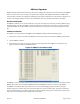
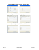
4. Open a HyperTerminal com:n connection using serial I/O parameters that are compatible with the serial port
setup at the HQ Plus and ST Plus devices (See “HyperTerminal” on page 32.).
5. Enter AT, ATZ, and ATH0 commands:
• Enter “AT”. The response should be “OK”. This response indicates that the HQ (modem) is ready and operating nor-
mally.
• Enter the "tel" number of the ST Plus to which the HQ Plus is to connect, (for example, ATDT5551234). The
response should be "CONNECTED ...".
6. Type some ASCII Text - the characters that are typed will be echoed back, as long as the loopback termination is in
place on the ST Plus. Also, the TX and RX LEDs on the HQ Plus and ST Plus devices will both flicker to indicate that
data is being transmitted and received. Lower baud rates will be indicated by longer LED "on" times.