Operator’s Manual / Manual Del Operador EN p. 2 26cc-2 Cycle Grass Trimmer NPTGCP2617A ES p. 41 Bordeadora con motor de 2 tiempos de 26 cc NPTGCP2617A NOTICE: Only use unleaded gasoline containing up to 10% ethanol. Do not use E15 or E85 fuel in this trimmer. It will violate the federal law, damage the trimmer and void your warranty. AVISO: Utilice solo gasolina sin plomo que contenga máximo 10% de etanol. No utilice combustible E15 o E85 con esta bordeadora.
CONTENTS Section Page CONTENTS PRODUCT SPECIFICATIONS GENERAL SAFETY RULES SYMBOLS KNOW YOUR GRASS TRIMMER ASSEMBLY BATTERY PACK AND CHARGER OPERATION MAINTENANCE ENVIRONMENTALLY SAFE BATTERY DISPOSAL TROUBLESHOOTING WARRANTY EXPLODED VIEW PARTS LIST EXPLODED VIEW 26CC 2-CYCLE ENGINE PARTS LIST 26CC 2-CYCLE ENGINE NOTES 2 2 3-6 7-8 9-10 11-14 14-15 16-22 23-30 31 32-33 34 35 36 37 38 39-40 PRODUCT SPECIFICATIONS 26cc-2 CYCLE GRASS TRIMMER Engine Size Engine Displacement Power / Speed Idle Speed Max Torq
GENERAL SAFETY RULES WARNING READ ALL INSTRUCTIONS AND SAVE THESE INSTRUCTIONS. Read the Operator’s Manual and follow all warnings and safety instructions. Failure to do so can result in serious injury to the operator and/or bystanders. ■ This grass trimmer is designed for cutting grass, soft vegetation. ■ The grass trimmer is intended for residential, or similar landscape use and is not recommended for use in agricultural or forest environments.
GENERAL SAFETY RULES ■ Never operate the grass trimmer with damaged guards or without the guards in place. ■ Maintain a firm grip on both handles while using this tool. ■ Keep firm footing and balance. Do not overreach. Overreaching can result in loss of balance or exposure to hot surfaces. ■ Maintain stable footing on a solid surface at all times when using the trimmer in order to have better control of the tool. Do not use the trimmer whilst on a ladder or other unstable support.
GENERAL SAFETY RULES ■ Do not dispose of battery packs in fire. They will explode or leak and cause injury. Liquid ejected from the battery may cause irritation or burns. ■ Do not crush, drop or damage the battery pack. Do not use a battery pack or charger that has been dropped or received a sharp blow. A damaged battery is subject to explosion. Properly dispose of a dropped or damaged battery immediately. ■ Batteries can explode in the presence of a source of ignition, such as a pilot light.
GENERAL SAFETY RULES identical model as listed in this manual. ■ A charger that is suitable for one type of battery pack may create a risk of fire when used with another battery pack. ■ Charge the battery at the normal charging temperature between 40°F (4°C) and 100°F (38°C). FCC COMPLIANCE ■ This device complies with Part 15 of the FCC Rules.
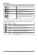
SYMBOLS Some of the following symbols may be used on this product. Please study them and learn their meaning. Proper interpretation of these symbols will allow you to operate the product better and safer. NAME SYMBOL DESIGNATION/EXPLANATION V Volts Voltage A Amperes Current Hz Hertz Frequency (cycles per second) W Watt Power hrs Hours Time /min Per Minute Revolutions, strokes, surface speed, orbits etc.
SYMBOLS Keep Away From Water Do not dispose of battery packs in rivers or immerse in water. Keep Away From Fire Do not dispose of battery packs in fire. They will explode or leak and cause injury. Heat Alert Do not expose battery packs to heat in excess of 140°F (60°C). Recycle Symbol This product uses lithium-ion batteries. Local, state, or federal laws may prohibit disposal of batteries in ordinary trash.
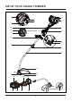
KNOW YOUR GRASS TRIMMER 4 5 1 6 2 3 21 7 20 8 19 18 9 10 17 11 12 13 14 15 16 22 29 23 28 27 24 26 25 9
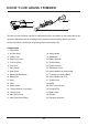
KNOW YOUR GRASS TRIMMER 32 30 31 33 The safe use of this product requires an understanding of the information on the product and in this Operator’s Manual as well as knowledge of the project you are attempting. Before use of this product, familiarize yourself with all operating features and safety rules. Components 1. Primer Bulb 2. Air Filter Knob 18. Assist Handle 3. Choke Lever 19. Start Button 4. Spark Plug Cover 20. Battery Indicator 5. Fuel Tank Cap 21. Throttle Safety 6. Fuel Tank 22.
ASSEMBLY This product requires assembly. ■ Carefully remove the product and any accessories from the box. Make sure that all items listed in the packing list are included. ■ Inspect the product carefully to make sure no breakage or damage occurred during shipping. ■ Do not discard the packing material until you have carefully inspected and satisfactorily operated the product. ■ If any parts are damaged or missing, please call the service center.
ASSEMBLY ■ Slide the debris guard onto the curved shaft all the way down to the correct mounting position as shown (Fig. 1). ■ Align the screw hole on the debris guard with the screw hole on the bracket. Insert the screw through the grass deflector and the bracket on the shaft (Fig. 2). ■ Secure the screw tight using the screwdriver (Fig. 3). Hole on the bracket Hole on the debris guard Fig. 1 Fig. 2 Fig. 3 INSTALLING AND REMOVING THE SHAFT (See Figs.
ASSEMBLY NOTE: If the button does not release completely in the positioning hole, the shafts are not locked into place. Slightly rotate from side to side until the button is locked into place. ■ Secure the shafts tight using the knob by turning it clockwise (Fig. 6). Tight Button Positioning Hole Loosen Fig. 5 Fig. 6 Ensure that the knob is fully tightened before operating the tool; check it periodically for tightness during use to avoid serious personal injury.
ASSEMBLY ADJUSTING THE ASSIST HANDLE (See Figs. 9-10) Never adjust the assist handle while the trimmer head is running. Failure to stop the engine may cause serious personal injury. Handle Position Handle Position The assist handle is pre-installed at delivery. Inspect and adjust it before operation if necessary. ■ Release the assist handle cam lock. ■ Adjust the assist handle using the anti-vibration ball to your most comfortable position as shown (Fig. 9). ■ Secure the assist handle cam lock.
BATTERY PACK AND CHARGER CHARGER LEDS ■ If the battery is not connected to the charger, a continuous green LED light indicates that the plug is plugged into an outlet socket and the battery charger is ready for operation. ■ Charging: a continuous red LED on the charger indicates that the battery is charging normally. ■ Charged: a continuous green LED on the charger indicates that the battery is ready for use.
OPERATION Do not allow familiarity with products to make you careless. Remember that a careless fraction of a second is sufficient to inflict serious injury. Always wear eye protection with side shields marked to comply with ANSI Z87.1, along with head protection. Failure to do so could result in objects being thrown into your eyes and other possible serious injuries. Do not use any attachments or accessories not recommended by the manufacturer or retailer of this product.
OPERATION Recommended Fuel This engine is certified to operate on unleaded gasoline intended for automotive use. U.S. EPA regulations make it illegal to use gasoline containing higher than 10% ethanol content in outdoor power equipment like your LawnMaster® power equipment and doing so can void your LawnMaster® Limited Warranty. If the proper precautions are taken, however, gasoline containing a 10% quantity of ethanol can safely be used in your LawnMaster® products.
OPERATION FILLING THE FUEL TANK (See Fig. 14) NOTICE: Before each use, ALWAYS shake the fuel container thoroughly to ensure that the fuel is mixed completely. ■ Place the tool on a flat, level surface, outdoors. Ensure the fuel tank and the shaft are in the same level so enough fuel can be filled into the fuel tank. ■ Clean the area around the fuel tank and cap to prevent any contamination. ■ Loosen the fuel tank cap by turning it counter clockwise and remove (Fig. 14). Gasket Fig.
OPERATION STARTING AND STOPPING THE GRASS TRIMMER (See Figs. 15-20) For cold start: ■ Make sure that the battery pack is securely in place. ■ Place the trimmer on a levelled surface, outdoors. ■ Press the primer bulb 5 times. ■ Turn the choke lever to the CHOKE position (Fig. 15). ■ Lift the start button cover and press the start button until the engine starts. Then immediately engage the throttle safety and the throttle trigger to start the trimmer (Fig. 16-19).
OPERATION ■ Lift the start button cover and press the start button until the engine starts. Then immediately engage the throttle safety and the throttle trigger to start the trimmer. STOP To stop the trimmer: Press the STOP switch to the stop position “O” until the trimmer stops (Fig. 20). BATTERY INDICATOR (See Fig. 21) Fig. 20 A battery indicator is located above the start button, and can be used to indicate the battery status (Fig. 21).
OPERATION ■ Always operate the trimmer in RUN position. When cutting long grass, work in stages from top to bottom in small sections. This will prevent the grass being cut from wrapping around the shaft and the spool head. ■ Hold the grass trimmer head at an angle of approximately 30° to the ground. Avoid pressing it against the ground as this can ruin the lawn and damage the product.
OPERATION Fig. 24 To advance the cutting line manually: ■ Stop the engine completely. ■ Push the spool cover in while pulling on the line, until you reach the desired length. NOTE: After each use, clean the trimmer head with a damp cloth to remove dirt and grime. CUTTING BLADE (See Fig. 25) The trimming line cutting blade is attached to the underside of the debris guard (Fig. 25). The cutting blade trims the line at a length that yields optimum cutting results.
MAINTENANCE Normal maintenance, replacement or repair of emission control devices and systems may be performed by an authorized service center or qualified individual that uses identical parts. Warranty repairs must be performed by an authorized service center; please contact your service dealer for assistance or Customer Service (Toll Free Number 866-384-8432). When servicing, use only identical replacement parts. Use of any other parts may create a hazard or cause product damage.
MAINTENANCE BATTERY MAINTENANCE ■ Store the battery pack fully charged. ■ Charge the battery pack whenever there is a noticeable reduction in the trimming performance. Do not allow the battery pack to become completely discharged. ■ Once the battery pack is fully charged, remove the battery from the charger and disconnect the charger from the outlet. ■ Do not store the battery pack on the tool or on the charger. ■ Charge the battery at a temperature between 40°F (4°C) and 100°F (38°C).
MAINTENANCE ■ Refer to the Line Replacement section in this manual if only the line needs to be replaced. ■ Insert the new spool into the spool cover. Release both trimming lines from the parking slot and guide the lines into both eyelets (Fig. 28). ■ To reinstall the spool cover, first align the arc area on the spool cover with the locking tabs on the trimmer head housing as shown. Then press the locking tabs and push the spool cover onto the trimmer head housing. Make sure they are secured tightly (Fig.
MAINTENANCE (RH) Winding Direction (RH) Fig. 31 Fig. 32 NOTE: Always clean the main spool cover and trimmer head housing before reassembling the trimmer head. NOTE: Always clean the trimmer head before replacing the spool. ■ Check the spool cover, spool and trimmer head housing for wear and replace parts if necessary. Install the spool in the spool cover and replace as described in the Spool Replacement section. NOTE: Only use the appropriate cutting line specified in this manual.
MAINTENANCE fire prevention regulations. Check with appropriate authorities. Contact Customer Service or your authorized service center to purchase a replacement spark arrestor. If the trimmer appears less efficient or powerful, it may be due to the build-up of carbon deposits around the exhaust port and muffler. This may occur depending on the type of fuel used, the type and amount of lubricant used, or the operating conditions.
MAINTENANCE ■ Place the air filter back, ensuring that it properly seated onto the air filter cover. Installing the filter correctly will decrease the chances of engine wear caused by dirt entering the engine (Fig. 37). ■ Replace the air filter cover ensuring the air filter is completely covered (Fig. 38). ■ Turn the air filter knob clockwise to secure the air filter cover. Fig. 37 Fig. 38 FUEL TANK CAP, TANK AND LINES DANGER Fuel is EXTREMELY flammable.
MAINTENANCE with a new one. DO NOT use a blowing tool to clean as the movement of dirt may damage the engine. ■ Adjust spark plug gap by bending outer electrode (Fig. 41). Fig. 39 Fig. 40 Fig. 41 Fig. 42 Outer Electrode 0.026 in. (0.65 mm) ■ Reinstall the cleaned or a new spark plug by turning it clockwise into place (Fig. 42). ■ Reinstall the spark plug cap into place. ■ Reinstall the spark plug cover and secure it with the hex wrench. NOTICE: Be careful not to cross-thread the spark plug.
MAINTENANCE HIGH ALTITUDE ENGINE OPERATION Initially your engine is configured for operation below 2000 ft. altitude. If the trimmer is being used above 2000 ft. altitude, the engine must be re-configured accordingly. Operating the engine with the wrong engine configuration at a given altitude may increase its emissions, drop fuel efficiency, reduce performance and cause irreparable damage. Engines configured for high altitude operation will need to be reconfigured for use in standard altitude conditions.
ENVIRONMENTALLY SAFE BATTERY DISPOSAL The following toxic and corrosive materials are in the batteries used in this battery pack: Lithium-ion, a toxic material. All toxic materials must be disposed of in a specified manner to prevent contamination of the environment. Before disposing of damaged or worn out Lithium-ion battery packs, contact your local waste disposal agency, or the local Environmental Protection Agency for information and specific instructions.
TROUBLESHOOTING If your grass trimmer does not appear to operate properly, follow the instructions below. If this does not solve the problem, please contact your local repair agent. Before proceeding, shut off the engine, wait for all moving parts to stop, and remove the battery pack. Failure to follow these instructions can result in serious personal injury or property damage. PROBLEM POSSIBLE CAUSE SOLUTION The battery is not inserted. Insert the battery correctly. Ensure the battery is fully charged.
TROUBLESHOOTING The engine starts, runs, and accelerates but will not idle. The line will not advance. The grass wraps around the drive shaft housing and the trimmer head. The spark arrestor screen is dirty. Contact an authorized service dealer. The idle speed screw on carburetor needs adjustment. Contact an authorized service dealer. The line is welded to itself. Lubricate the line with silicone spray. Insufficient cutting line. Install more line.
WARRANTY LawnMaster® No-Pull™ LIMITED WARRANTY We take pride in producing a high quality, durable product. This LawnMaster® product carries a limited three (3) year warranty against defects in workmanship and materials from date of purchase under normal household use. This product carries a ninety (90) day warranty from the date of purchase when used for commercial or rental purposes. Batteries and chargers carry a two-year warranty against defects in workmanship and materials from date of purchase.
EXPLODED VIEW NPTGCP2617A EXPLODED VIEW 35
PARTS LIST NPTGCP2617A MANUAL PARTS LIST Key Number Part Number Description Quantity 1 321001101 Cleva 26cc 2-Cycle Engine 1 2 321001102 Throttle-body & Starter Set 1 2.1 321001103 Throttle-body Set 1 2.2 321001104 Starter Set 1 2.2.1 321001105 Electric Switch 1 2.2.2 321001106 Starter Switch Assembly 1 2.2.3 321001107 Stop Switch Set 1 2.2.4 321001108 PCB Assembly 1 3 321001109 Handle Spacer 2 4 321001110 Cable Clamp 2 5 321001111 Clutch Assembly 1 5.
EXPLODED VIEW 26CC 2-CYCLE ENGINE 37
PARTS LIST 26CC 2-CYCLE ENGINE 26CC 2-CYCLE ENGINE PART LIST Key Number 1 2 3 4 5 6 7 8 9 10 11 12 13 14 15 16 17 18 19 20 21 22 23 24 25 26 27 28 29 30 31 32 33 34 35 36 37 Part Number 321001130 321001131 321001132 321001136 321001137 321001138 321001139 321001147 321001148 321001149 321001150 321001151 321001152 321001156 321001160 321001161 321001162 321001163 321001164 321001165 321001166 Description Spark Plug Cover Nut Upper Engine Cover Logo Air Deflector Cylinder Assembly Muffler Cover Muffler
NOTES 39
NOTES 40
CONTENTS Sección Página CONTENIDOS Especificaciones del producto Reglas generales de seguridad Símbolos Conozca su bordeadora Armado Batería y cargador Funcionamiento Mantenimiento Eliminación ambientalmente segura de la batería Resolución de problemas Garantía Vista en detalle Lista de piezas Vista en detalle del motor de 2 tiempos de 26 cc Lista de piezas del motor de 2 tiempos de 26 cc Notas 41 41 42-45 46-47 48-49 50-53 53-54 55-61 62-69 70 71-72 73 74 75 76 77 78-79 ESPECIFICACIONES DEL PRODUCTO BO
REGLAS GENERALES DE SEGURIDAD ADVERTENCIA LEA TODAS LAS INSTRUCCIONES y GUÁRDELAS. Lea el manual del usuario y siga todas las advertencias e instrucciones de seguridad. No hacerlo puede provocar lesiones graves al operador o a las personas en las cercanías. ■ Esta bordeadora está diseñada para cortar pasto y vegetación suave. ■ La bordeadora está hecha para uso residencial o en entornos similares y no se recomienda para entornos forestales o agrícolas.
REGLAS GENERALES DE SEGURIDAD ■ ■ ■ ■ ■ ■ ■ ■ ■ ■ ■ ■ ■ ■ ■ ■ alambre o cables de cobre que puedan romperse y convertirse en un proyectil peligroso. Utilice la bordeadora sólo durante el día o bajo una buena iluminación artificial. Jamás utilice la bordeadora si las protecciones están dañadas o no están puestas. Al usar esta herramienta, mantenga un agarre firme sobre ambas empuñaduras. Párese firmemente y de manera equilibrada. No se extralimite.
REGLAS GENERALES DE SEGURIDAD ■ ■ ■ ■ ■ ■ ■ ■ ■ ■ manual. Un cargador que es adecuado para un tipo de paquete de batería puede crear riesgo de incendio si se utiliza con otro paquete de batería diferente. No coloque herramientas a batería ni sus baterías cerca del fuego o calor. Esto reducirá el riesgo de explosión y posibles lesiones. No abra ni desarme la batería. Los electrolitos liberados son corrosivos y pueden dañar los ojos o la piel. Puede ser tóxico si se ingiere.
REGLAS GENERALES DE SEGURIDAD ■ No utilice un cargador que se haya caído o recibido un golpe duro. ■ No desarme el cargador. Llévelo a un centro de servicio calificado para que lo revisen o cambien. Un procedimiento de reensamblaje incorrecto puede provocar descargas eléctricas o incendios. ■ No maltrate el cable del cargador. Jamás utilice el cable para transportar el cargador, para tirar del cargador o para desconectar el cargador.
SÍMBOLOS Algunos de los siguientes símbolos podrían aparecer en este producto. Estúdielos y aprenda su significado. La interpretación adecuada de estos símbolos le permitirá utilizar el producto de mejor manera y con más seguridad. NOMBRE SÍMBOLO DESIGNACIÓN/EXPLICACIÓN V Volts Voltaje A Amperes Corriente Hz Hertz Frecuencia (ciclos por segundo) W Vatio Energía hrs Horas Tiempo /min Por minuto Revoluciones, tiempos, velocidad de la superficie, órbitas, etc.
SÍMBOLOS Mantener alejado del agua No elimine las baterías lanzándolas a ríos ni las sumerja en agua. Mantener alejado del fuego No elimine las baterías utilizando fuego. Explotarán o tendrán fugas y provocarán lesiones. Alerta de calor No exponga baterías a un calor mayor a 60ºC (140 ºF). Símbolo de reciclaje Este producto utiliza baterías de iones de litio. Las leyes locales, estatales o federales podrían prohibir la eliminación de baterías junto con la basura común.
CONOZCA SU BORDEADORA 4 5 1 6 2 3 21 7 20 8 19 18 9 10 17 11 12 13 14 15 16 22 29 23 28 27 24 26 25 48
CONOZCA SU BORDEADORA 32 30 31 33 El uso seguro de este producto requiere que conozca la información de la herramienta y la que aparece en este manual del usuario, así como también el proyecto en el que está trabajando. Antes de usar este producto, familiarícese con todas las funciones operativas y reglas de seguridad. Componentes 1. Pulsador de cebado 18. Manilla de apoyo 2. Perilla del filtro de aire 19. Botón de arranque 3. Palanca de ahogue 20. Indicador de la batería 4. Tapa de la bujía 21.
ARMADO Este producto requiere armado. ■ Con cuidado, extraiga el producto y sus accesorios de la caja. Asegúrese de que todos los elementos mencionados en la lista de componentes del empaque estén incluidos. ■ Inspeccione el producto cuidadosamente para asegurarse de que no se haya roto o dañado durante el transporte. ■ No bote el material del empaque hasta que haya inspeccionado completamente y utilizado satisfactoriamente el producto. ■ Si alguna pieza está dañada o faltante, llame al centro de servicio.
ARMADO ■ Suelte y quite el tornillo de la protección contra sedimentos usando el destornillador incluido. ■ Deslice la protección contra sedimentos hacia el eje curvo hasta el fondo hacia la posición de montaje correcta como se indica en la imagen (Fig. 1). ■ Alinee el orificio para el tornillo de la protección contra sedimentos con el orificio para el tornillo de la abrazadera. Inserte el tornillo a través del deflector de pasto y de la abrazadera del eje (Fig. 2).
ARMADO NOTA: Si el botón no se suelta del todo en el orificio de posición, los ejes no están fijados en su lugar. Gire lentamente de lado a lado hasta que el botón calce en su lugar. ■ Fije los ejes con firmeza usando la perilla, girándola hacia la derecha (Fig. 6). Apriete Botón Orificio de posicionamiento Fig. 5 Suelte Fig.
ARMADO AJUSTE DE LA MANILLA DE APOYO (Consulte las Figuras 9-10) ADVERTENCIA Jamás ajuste la manilla de apoyo mientras el cabezal de la bordeadora está andando. No detener el motor puede provocar lesiones personales graves. Handle Position Handle Position La manilla de apoyo viene preinstalada. En caso de ser necesario, inspeccione y ajústela antes de usar el producto. ■ Suelte el cerrojo de leva de la manilla de apoyo.
BATERÍA Y CARGADOR LED DE CARGA ■ Si la batería no está conectada al cargador, una luz LED verde continua indica que el enchufe está conectado en una toma de corriente y que el cargador está listo para funcionar. ■ Cargando: un LED rojo continuo en el cargador indica que la batería está cargando normalmente. ■ Cargada: un indicador LED verde continuo en el cargador indica que la batería está lista para usarse.
FUNCIONAMIENTO ADVERTENCIA No permita que estar acostumbrado a usar un producto genere descuidos en usted. Recuerde que una sola fracción de segundo en que se descuide es suficiente para generar una lesión severa. ADVERTENCIA Use siempre protección ocular con escudos laterales para cumplir con la normativa ANSI Z87.1, junto con protección para la cabeza. Si no lleva protección, pueden saltarle objetos a los ojos y sufrir otras posibles lesiones graves.
FUNCIONAMIENTO Prepare solo cantidades que puedan usarse en un lapso de pocos días. NO prepare cantidades que deberán almacenarse durante más de 30 días. Combustible recomendado Este motor tiene certificación para usarse con gasolina automotriz sin plomo.
FUNCIONAMIENTO LLENADO DEL TANQUE DE COMBUSTIBLE (Consulte la Figura 14) AVISO: antes de cada uso, agite SIEMPRE el contenedor de combustible exhaustivamente para garantizar que la gasolina se mezcle por completo. ■ Coloque la herramienta sobre una superficie plana y estable en exteriores. Asegúrese de que el tanque de combustible y el eje estén al mismo nivel, para que pueda entrar suficiente combustible en el tanque.
FUNCIONAMIENTO ARRANQUE Y DETENCIÓN DE LA BORDEADORA (Consulte las Figuras 15-20) Para un arranque en frío: ■ Asegúrese de que la batería esté bien asegurada. ■ Coloque la bordeadora sobre una superficie nivelada en exteriores. ■ Presione el pulsador de cebado 5 veces. ■ Mueva la palanca de ahogue hacia la posición CHOKE (Fig. 14). Fig. 15 ■ Levante la tapa del botón de arranque y presione el botón de arranque hasta que el motor encienda.
FUNCIONAMIENTO ■ Asegúrese de que la palanca de ahogue esté en la posición RUN. ■ Levante la tapa del botón de arranque y presione el botón de arranque hasta que el motor encienda. Luego, active inmediatamente el seguro y el gatillo del acelerador para arrancar la bordeadora. Para detener la bordeadora: Presione el interruptor STOP hacia la posición “O” hasta que la bordeadora se detenga (Fig. 20).
FUNCIONAMIENTO ■ Sostenga la bordeadora con firmeza usando ambas manos, manteniendo su mano derecha sobre la manila principal y su mano izquierda sobre la manila de apoyo. ■ La bordeadora debe sostenerse en posición cómoda, con la manilla posterior a nivel de la cadera (Fig. 22). ■ Use siempre la bordeadora en posición RUN. Cuando corte pasto largo, trabaje en etapas de arriba a abajo en secciones pequeñas. Esto evitará que el pasto cortado se enrolle en el eje y cabezal del carrete.
FUNCIONAMIENTO hilo contra el suelo (Fig. 24). NO mantenga el cabezal de la bordeadora presionado contra el piso. AVISO: La hoja de corte de la parte inferior de la protección contra sedimentos cortará el hilo al largo correcto. AVISO: Un hilo demasiado corto podría no avanzar usando el método de presión y podría ser necesario hacerlo manualmente. Fig. 24 Para hacer avanzar el hilo manualmente: ■ Detenga el motor. ■ Empuje la tapa del carrete mientras tira del hilo, hasta alcanzar el largo deseado.
MANTENIMIENTO El mantenimiento normal, los cambios de piezas o la reparación de los sistemas y dispositivos de control de emisiones se deben realizar mediante un centro de servicio calificado o persona calificada que use piezas idénticas. Las reparaciones de garantía se deben realizar mediante un centro de servicio autorizado; contacte a su representante de ventas local para obtener ayuda, o bien al servicio de atención al cliente (llamada gratuita al 866-384-8432).
MANTENIMIENTO MANTENIMIENTO DE LA BATERÍA ■ Almacene la batería hasta que esté cargada por completo. ■ Cargue la batería cuando haya una reducción notable en el desempeño de la bordeadora. No deje que la batería se descargue por completo. ■ Cuando la batería se cargue por completo, extraiga la batería del cargador y desconéctelo de la toma de corriente. ■ No almacene la batería puesta en la herramienta o en el cargador. ■ Cargue la batería a una temperatura entre 4°C (40°F) y 38°C (100°F).
MANTENIMIENTO ■ Si necesita cambiar solo el hilo, consulte la sección Cambio del hilo de este manual. ■ Inserte un nuevo carrete hacia la tapa del carrete. Suelte ambos hilos de corte desde la ranura de asentamiento y guíelas hacia ambos ojales (Fig. 28). ■ Para reinstalar la tapa del carrete, primero alinee el área de arco de la tapa del carrete con las lengüetas de bloqueo en la carcasa del cabezal de la bordeadora, como se indica en la imagen.
MANTENIMIENTO (RH) Dirección de enrollado (RH) Fig. 31 Fig. 32 NOTA: Limpie siempre la tapa principal del carrete y la carcasa del cabezal de la bordeadora antes de reensamblar el cabezal. NOTA: Limpie siempre el cabezal de la bordeadora antes de reinstalar el carrete. ■ Revise que no haya desgaste en la tapa del carrete, carrete y carcasa del cabezal de la bordeadora; de ser necesario, reemplace las piezas que así lo requieran.
MANTENIMIENTO EE.UU., y no puede usarse en los terrenos boscosos de dicho país. Además, los usuarios del producto deben cumplir con las leyes de prevención de incendios locales, estatales y federales. Consulte a las autoridades locales sobre estos asuntos. Contacte al servicio de atención al cliente o a su centro de servicio autorizado para comprar o reemplazar el protector contra chispas.
MANTENIMIENTO NOTA: Inspeccione el filtro para asegurarse de que no tenga daños; de ser necesario, reemplácelo por uno nuevo. ■ Limpie el filtro de espuma con agua jabonosa y enjuague. Seque el filtro al aire. ■ Coloque el filtro en su lugar, asegurándose de asentarlo correctamente sobre la tapa del filtro de aire. Instalar el filtro correctamente reducirá la probabilidad de que el motor se desgaste por culpa de que entre suciedad en él (Fig. 37).
MANTENIMIENTO CAMBIO DE LA BUJÍA (Consulte las Figuras 39-42) La bujía de este motor se puede cambiar usando una equivalente o idéntica a la original. La brecha de la bujía debe ser de 0,65 mm (0,026 in). Cámbiela una vez al año por una pieza recomendada o equivalente. ■ Quite la tapa de la bujía usando la llave hexagonal incluida (Fig. 39). ■ Quite el tapón de la bujía. Cubra completamente la bujía usando la manga incluida. Gire la manga hacia la izquierda para sacar la bujía (Fig. 40).
MANTENIMIENTO FUNCIONAMIENTO DEL MOTOR EN LUGARES DE GRAN ALTITUD Inicialmente, su motor está configurado para funcionar bajo 600 metros (2000 ft) de altitud. El motor deberá reconfigurarse si la bordeadora se usará por sobre 600 metros de altitud. Usar el motor en la configuración incorrecta a una altitud dada puede aumentar sus emisiones, reducir la eficiencia del combustible, disminuir el rendimiento y causar daños irreparables.
ELIMINACIÓN AMBIENTALMENTE SEGURA DE LA BATERÍA Los siguientes materiales tóxicos y corrosivos están presentes en esta batería: Iones de litio, material tóxico. ADVERTENCIA Todos los materiales tóxicos deben eliminarse de la manera especificada a fin de evitar contaminación al ambiente. Antes de eliminar una batería de litio dañada o gastada, contacte a su agencia local de eliminación de desechos o a la agencia local de protección ambiental para obtener información sobre las instrucciones específicas.
RESOLUCIÓN DE PROBLEMAS Si su bordeadora de pasto no parece funcionar apropiadamente, siga estas instrucciones. Si esto no resuelve el problema, comuníquese con su agente de reparaciones local. ADVERTENCIA Antes de continuar, apague el motor, espere que todas las piezas móviles se detengan y quite la batería. El no seguir estas instrucciones puede causar lesiones severas o daños a la propiedad. PROBLEMA PROBLEMA El motor no arranca. El motor no alcanza la velocidad máxima y emite demasiado humo.
RESOLUCIÓN DE PROBLEMAS El motor arranca, funciona y acelera, pero no entra en ralentí. El hilo no avanza. El pasto se enrolla en la carcasa del eje motriz y en el cabezal de la bordeadora. El protector contra chispas está sucio. Contacte a un centro de servicio autorizado. El tornillo regulador de la velocidad en ralentí debe ajustarse. Contacte a un centro de servicio autorizado. El hilo está pegado entre sí. Lubrique el hilo con un atomizador de silicona líquida.
GARANTÍA GARANTÍA LIMITADA LawnMaster® No-Pull™ Nos sentimos orgullosos de ofrecer a usted un producto de alta calidad y durabilidad. Este producto Lawnmaster® posee una garantía limitada de tres (3) años contra defectos de fabricación y materiales a contar de la fecha de compra, bajo uso doméstico normal. Este producto posee una garantía de noventa (90) días a contar de la fecha de compra cuando se usa para propósitos comerciales o de alquiler.
VISTA EN DETALLE NPTGCP2617A VISTA EN DETALLE 74
LISTA DE PIEZAS LISTA DE PIEZAS DE LA BORDEADORA NPTGCP2617A Número clave Número de la pieza Descripción Cantidad 1 321001101 Motor Cleva de 26cc de 2 tiempos 1 2 321001102 Conjunto del cuerpo del acelerador y arranque 1 2.1 321001103 Conjunto del cuerpo del acelerador 1 2.2 321001104 Conjunto del arranque 1 2.2.1 321001105 Interruptor eléctrico 1 2.2.2 321001106 Conjunto de piezas del interruptor de arranque 1 2.2.3 321001107 Conjunto del interruptor de parada 1 2.2.
VISTA EN DETALLE DEL MOTOR DE 2 TIEMPOS DE 26 CC 76
LISTA DE PIEZAS DEL MOTOR DE 2 TIEMPOS DE 26 CC LISTA DE PIEZAS DEL MOTOR DE 2 TIEMPOS DE 26 CC Número clave Número de la pieza 1 2 3 4 5 6 7 8 9 10 11 12 13 14 15 16 17 18 19 20 21 22 23 24 25 26 27 28 29 30 31 32 33 34 35 36 37 321001130 321001131 321001132 321001136 321001137 321001138 321001139 321001147 321001148 321001149 321001150 321001151 321001152 321001156 321001160 321001161 321001162 321001163 321001164 321001165 321001166 Descripción Cantidad Tapa de la bujía Tuerca Cubierta superior d
NOTAS 78
NOTAS 79