
User Manual

GENERAL TECHNICAL DESCRIPTION
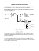
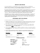
The LM3 provides for three unbalanced, mono or stereo inputs to be mixed into either one or both the Main and
Aux outputs. Each stereo signal is summed to mono and then passed through the Main Output and Aux Output
level controls. Each input can provide up to 15dB gain, to boost weak signals to acceptable levels.
The amount of the mono signals that is sent to the Main and Aux buses is controlled by the setting of the Main
Output or Aux Output level controls, respectively. Only audio quality operational amplifiers are used in the signal
path to maintain highest signal integrity.
AUX BUS
MAIN BUS
AUX
SEND BUFFER
MAIN
SEND BUFFER
LEFT
INPUT
RIGHT
INPUT
SUMMING AMP
+10dB GAIN
MAIN SEND
LEVEL
AUX SEND
LEVEL
+15V
+15V REGULATOR
+23V BUSS
Figure 1 - LM3 Block Diagram
-15V
-15V REGULATOR
-23V BUSS
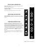
INSTALLATION
The LM3 module is installed from the rear of the Modular Audio Processor mainframe. The printed circuit board
can fit into any of the ten slots provided for Modular Audio Processor modules. Once the module is fit into the card
guides for the slot, it may be slid forward in the mainframe until the female edge connector seats firmly onto the
male pins of the main bus board.
Care should be taken when inserting the edge connector onto the pins to be sure there is correct alignment.
Two #2 machine screws with captive washers are provided to secure the rear panel of the LM3 to the top and
bottom rear rails of the Modular Audio Processor mainframe. Two #2 flat head screws are provided to secure the
front panel of the LM3 to the front panel of the Modular Audio Processor mainframe. Once these four screws are in
place, the installation of this module is complete.
2