SPEEDMASTER® SM SERIES SUB-MICRO INVERTERS Installation and Operation Manual
TABLE OF CONTENTS 1.0 GENERAL . . . . . . . . . . . . . . . . . . . . . . . . . . . . . . . . . . . . . . . . . . . . .1 2.0 SM Series™ DIMENSIONS . . . . . . . . . . . . . . . . . . . . . . . . . . . . . . . .3 4.0 SM Series™ SPECIFICATIONS . . . . . . . . . . . . . . . . . . . . . . . . . . . . .4 5.0 SM Series™ RATINGS . . . . . . . . . . . . . . . . . . . . . . . . . . . . . . . . . . . .5 6.0 INSTALLATION . . . . . . . . . . . . . . . . . . . . . . . . . . . . . . . . . . . . . . . .6 7.
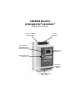
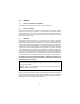
LEESON Electric SPEEDMASTER® SM SERIES™ SUB-MICRO DRIVE INPUT POWER TERMINALS DC BUS TERMINALS ELECTRONIC PROGRAMMING MODULE (EPM) 3-DIGIT LED DISPLAY PROGRAMMING BUTTONS CONTROL TERMINAL STRIP OUTPUT (MOTOR) TERMINALS
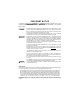
IMPORTANT NOTICE DANGER , WARNING and CAUTION information is supplied to you for your The following protection and to provide you with many years of trouble free and safe operation of your LEESON Electric product. DANGER • Hazard of electrical shock! Capacitors retain charge after power is removed. Disconnect incoming power and wait until the voltage between terminals B+ and B- is 0 VDC before servicing the drive.
1.0 GENERAL 1.1 PRODUCTS COVERED IN THIS MANUAL This manual covers the LEESON Electric SM Series™ Variable Frequency Drive. 1.2 PRODUCT CHANGES LEESON Electric reserves the right to discontinue or make modifications to the design of its products without prior notice, and holds no obligation to make modifications to products sold previously. LEESON Electric also holds no liability for losses of any kind which may result from this action.
1.5 SAFETY INFORMATION General All operations concerning installation and commissioning, as well as maintenance, must be carried out by qualified, skilled personnel (IEC 364 and CENELEC HD 384 or DIN VDE 0100 and IEC report 664 or DIN VDE 0110 and national regulations for the prevention of accidents must be observed).
1.6 CUSTOMER MODIFICATION LEESON Electric welcome the opportunity to assist our customers in applying our products. Many customizing options are available to aid in this function. LEESON Electric cannot assume responsibility for any modifications not authorized by its engineering department.
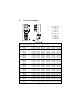
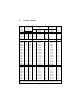
2.0 SM Series™ DIMENSIONS IF R < 6.30” (160) S = 0.19” (5) T = 0.38” (10) U = 0.18” (5) V = 0.66” (17) IF R = 6.30” (160) S = 0.28” (7) T = 0.50” (13) U = 0.24” (6) V = 0.90” (23) HP INPUT INPUT SM (kW) VOLTAGE PHASE MODEL H W 0.33 120 1 174263 5.75 (146) 2.88 (74) (0.25) 208/240 1 174267 5.75 (146) 2.88 (74) 120 1 174264 5.75 (146) 2.88 (74) 0.5 208/240 1 174268 5.75 (146) 2.88 (74) (0.37) 208/240 3 174274 5.75 (146) 2.88 (74) 400/480 3 174281 5.75 (146) 2.88 (74) 120 1 174265 5.75 (146) 3.
4.0 SM Series™ SPECIFICATIONS Storage Temperature Ambient Operating Temperature Ambient Humidity Altitude Input Line Voltages Input Voltage Tolerance Input Frequency Tolerance Output Wave Form Output Frequency Carrier Frequency Service Factor Efficiency Power Factor (displacement) Overload Current Capacity Speed Reference Follower Digital Outputs Earth Leakage Current (EN 50178) Conformity Approvals -20° to 70° C 0° to 40° C (derate 2.
5.0 SM Series™ RATINGS SM MODEL FOR MOTORS NUMBER RATED (NOTE 1) HP kW 120 Vac INPUT MODELS 174263 0.33 0.25 174264 0.50 0.37 174265 1 0.75 174266 1.5 1.1 208/240 Vac INPUT MODELS 174267 0.33 0.25 174268 0.50 0.37 174274 0.50 0.37 174270 1 0.75 174276 1 0.75 174271 1.5 1.1 174277 1.5 1.1 174272 2 1.5 174278 2 1.5 174273 3 2.2 174279 3 2.2 174288 5 4.0 174280 7.5 5.5 174290 10 7.5 174292 15 11 400/480 Vac INPUT MODELS 174281 0.50 0.37 174282 1 0.75 174283 1.5 1.1 174284 2 1.5 174286 3 2.2 174287 5 4.
6.0 INSTALLATION NOTE: SM Series™ drives are intended for inclusion within other equipment, by professional electrical installers according to EN 61000-3-2. They are not intended for stand-alone operation. WARNING DRIVES MUST NOT BE INSTALLED WHERE SUBJECTED TO ADVERSE ENVIRONMENTAL CONDITIONS SUCH AS: COMBUSTIBLE, OILY, OR HAZARDOUS VAPORS OR DUST; EXCESSIVE MOISTURE OR DIRT; VIBRATION; EXCESSIVE AMBIENT TEMPERATURES.
7.0 INPUT AC POWER REQUIREMENTS DANGER Hazard of electrical shock! Capacitors retain charge after power is removed. Disconnect incoming power and wait until the voltage between terminals B+ and B- is 0 VDC before servicing the drive. The input voltage must match the nameplate voltage rating of the drive. Voltage fluctuation must not vary by greater than 10% overvoltage or 15% undervoltage.
7.2 INPUT FUSING AND DISCONNECT REQUIREMENTS A circuit breaker or a disconnect switch with fuses must be provided in accordance with the National Electric Code (NEC) and all local codes. Refer to the following tables for proper fuse/circuit breaker ratings and wire sizes.
7.3 INSTALLATION ACCORDING TO EMC REQUIREMENTS The SM Series™ Series can be installed to meet the European standards Electromagnetic Compatibility (EMC) requirements. These requirements govern the permissible electromagnetic emissions and immunity, both radiated and conducted, of a drive system. The EMC requirements apply to the final installation in its entirety, not to the individual components used.
8.1 INPUT AND OUTPUT WIRING On single phase input models, wire the input power to terminals L1 and L2/N. On three phase input models, wire the input power to terminals L1, L2, and L3. Refer to Section 9.0 - SM Series™ POWER WIRING DIAGRAM. All three power output wires, from terminals U, V, and W to the motor, must be kept tightly bundled and run in a separate conduit away from all other power and control wiring.
9.0 SM Series™ POWER WIRING DIAGRAM WARNING Do not connect incoming AC power to output terminals U, V, or W, or terminals B+, B-!. Severe damage to the drive will result. NOTES: 1. 2. 3. 4. 5. 6. WIRE AND GROUND IN ACCORDANCE WITH NEC OR CEC, AND ALL APPLICABLE LOCAL CODES. Motor wires MUST be run in a separate steel conduit away from control wiring and incoming AC power wiring. Do not install contactors between the drive and the motor without consulting LEESON Electric for more information.
10.0 CONTROL WIRING 10.1 CONTROL WIRING VS. POWER WIRING External control wiring MUST be run in a separate conduit away from all other input and output power wiring. If control wiring is not kept separate from power wiring, electrical noise may be generated on the control wiring that will cause erratic drive behavior. Use twisted wires or shielded cable grounded at the drive chassis ONLY. Recommended control wire is Belden 8760 (2-wire) or 8770 (3-wire), or equivalent. Strip off 0.20 to 0.
10.6 SPEED REFERENCE SELECTION If an analog speed reference input is used to control the drive speed, terminal TB-13A, 13B, or 13E (Parameter 10, 11, or 12) may be programmed as the input select for the desired analog input signal. When that TB-13 terminal is then closed to TB-11, the drive will follow the selected analog speed reference input.
NOTE: If TB-13A, TB-13B, and TB-13E are all programmed to select speed references, and two or three of the terminals are closed to TB-11, the higher terminal has priority and will override the others. For example, if TB-13A is programmed to select 0-10 VDC, and TB-13E is programmed to select PRESET SPEED #3, closing both terminals to TB-11 will cause the drive to respond to PRESET SPEED #3, because TB-13E overrides TB-13A.
11.0 SM Series™ CONTROL WIRING DIAGRAMS 11.1 SM Series™ TERMINAL STRIP Shown below is the control terminal strip, along with a brief description of the function of each terminal. The following wiring diagram examples provide a quick reference to wire the drive for the most common configurations.
11.2 TWO-WIRE START/STOP CONTROL 11 SIGNAL COMMON 0-10 VDC INPUT SPEED POT POWER SUPPLY DIGITAL INPUT REFERENCE MAINTAINED RUN/STOP CONTACT (FORWARD) 13A 13B 13E 25 4-20 mA INPUT 6 TB-13E FUNCTION SELECT 5 TB-13B FUNCTION SELECT 2 TB-13A FUNCTION SELECT (RUN REVERSE) 1 RUN FORM A RELAY 16 17 MAINTAINED RUN/STOP CONTACT (REVERSE) NOTES: 1. Close TB-1 to TB-11 to RUN and open to STOP.
11.3 THREE-WIRE START/STOP CONTROL 11 SIGNAL COMMON 0-10 VDC INPUT SPEED POT POWER SUPPLY DIGITAL INPUT REFERENCE 13A 13B REV MOMENTARY STOP CONTACT 13E 25 16 17 4-20 mA INPUT 6 TB-13E FUNCTION SELECT (START FORWARD) 5 TB-13B FUNCTION SELECT 2 TB-13A FUNCTION SELECT (START REVERSE) 1 STOP FORM A RELAY FWD MOMENTARY START CONTACT NOTES: 1. Program TB-13E (Parameter 12) for START FORWARD (06). 2.
11.4 PRESET SPEEDS AND SPEED POT (WITH TWO-WIRE START/STOP CONTROL) 13A 13B 13E 25 16 17 TB-13E FUNCTION SELECT (PRESET SPEED #3) 0-10 VDC INPUT 11 TB-13B FUNCTION SELECT (PRESET SPEED #2) SIGNAL COMMON 6 TB-13A FUNCTION SELECT (PRESET SPEED #1) 5 DIGITAL INPUT REFERENCE 2 SPEED POT POWER SUPPLY 1 RUN FORM A RELAY SPEED POT MAINTAINED RUN/STOP CONTACT NOTES: 1. For preset speed control, all or some of the TB-13 terminals must be programmed as preset speed selects.
12.0 INITIAL POWER UP AND MOTOR ROTATION WARNING DO NOT connect incoming AC power to output terminals U, V, and W or terminals B+, B-! Severe damage to the drive will result. Do not continuously cycle input power to the drive more than once every two minutes. Damage to the drive will result. DANGER Hazard of electrical shock! Wait three minutes after disconnecting incoming power before servicing drive. Capacitors retain charge after power is removed.
Follow the procedure below to check the motor rotation. This procedure assumes that the drive has been powered up for the first time, and that none of the parameters have been changed. 1. Use the M button to decrease the speed setpoint to 00.0 Hz. The left decimal point will illuminate as the speed setpoint is decreased. If the M button is held down, the speed setpoint will decrease by tenths of Hz until the next whole Hz is reached, and then it will decrease by one Hz increments.
13.0 PROGRAMMING THE SM Series™ DRIVE The drive may be programmed by one of two methods: using the three buttons and 3-digit LED display on the front of the display, or programming the Electronic Programming Module (EPM) using the optional EPM Programmer. This section describes programming the drive using the buttons and display, which are shown below: BUTTONS DISPLAY Mode To enter the PROGRAM mode to access the parameters, press the Mode button.
NOTE: If the display flashes “Er”, the password was incorrect, and the process to enter the password must be repeated. Use the L and M buttons to scroll to the desired parameter number. In the example below, Parameter 19 is being displayed, which is the ACCELERATION TIME of the drive: Use L and M to scroll to the desired parameter number (the example is Parameter 19 - ACCELERATION TIME) Once the desired parameter number is found, press the Mode button to display the present parameter setting.
13.1 SETTING VALUES IN TENTHS OF UNITS ABOVE 100 Parameter settings and the keypad speed command can always be adjusted in tenths of unit increments from 0.0 to 99.9. Above 100 however, values can be set in whole units or tenths of units, depending on the setting of Parameter 16 - UNITS EDITING. If Parameter 16 - UNITS EDITING is set to WHOLE UNITS (02), parameter values and the keypad speed command can only be adjusted by whole unit increments above 100.
13.2 ELECTRONIC PROGRAMMING MODULE (EPM) Every SM Series™ drive has an Electronic Programming Module (EPM) installed on the main control board. The EPM stores the user’s parameter settings and special OEM default settings (if programmed). The EPM is removable, allowing it to be installed in another drive for quick set-up. For example, if a drive is being replaced with a new one, the EPM can be taken out of the first drive and installed in the new drive.
14.0 PARAMETER MENU NO.
PARAMETER MENU (cont) NO. PARAMETER NAME RANGE OF ADJUSTMENT 12 TB-13E FUNCTION SELECT NONE (01), 0-10 VDC (02), 4-20mA (03), PRESET SPEED #3 (04), INCREASE FREQ (05), START FORWARD (06), EXTERNAL FAULT (07), INVERSE EXT FAULT (08), AUXILIARY STOP (09), ACCEL/DECEL #2 (10).
PARAMETER MENU (cont) NO. PARAMETER NAME RANGE OF ADJUSTMENT 30 31-37 38 39 42 44 45 46 47 48 SLIP COMPENSATION PRESET SPEEDS SKIP BANDWIDTH SPEED SCALING ACCEL / DECEL #2 PASSWORD SPD AT MIN SIGNAL SPD AT MAX SIGNAL CLEAR HISTORY PROGRAM SELECTION 50 51 52 53 54 55 56 57 58 FAULT HISTORY SOFTWARE CODE DC BUS VOLTAGE MOTOR VOLTAGE LOAD 0 - 10 VDC INPUT 4-20 mA INPUT TB STRIP STATUS KEYPAD STATUS 0.0 - 5.0 % 0.0 - MAXIMUM FREQUENCY 0.0 - 10.0 Hz 0.0 - 6500.0 0.1 - 3600.
15.0 DESCRIPTION OF PARAMETERS P01 LINE VOLTAGE SELECTION This calibrates the drive for the actual applied input voltage. Set this parameter to HIGH (01) for 120, 220-240, and 460-480 Vac input, or LOW (02) for 200-208 and 380-415 Vac input. NOTE: If this parameter is changed while the drive is running, the new value will not take effect until the drive is stopped. P02 CARRIER FREQUENCY This sets the switching rate of the output IGBT’s.
03 START WITH DC BRAKE: When a START command is given, the drive will apply DC BRAKE VOLTAGE (Parameter 22) for the duration of DC BRAKE TIME (Parameter 21) prior to starting the motor to ensure that the motor is not turning. 04 AUTO RESTART WITH DC BRAKING: Upon a START command, after a fault, or upon application of power, the drive will apply DC BRAKE VOLTAGE (Parameter 22) for the duration of DC BRAKE TIME (Parameter 21) prior to starting (or restarting) the motor.
04 P05 RAMP WITH DC BRAKE: When a stop command is given, the drive will decelerate the motor down to 0.2 Hz (at the rate set by Parameter 20 - DECELERATION TIME) and then activate DC braking according to the settings of Parameters 21 - DC BRAKE TIME and 22 DC BRAKE VOLTAGE. This is used to bring the load to a final stop, as the motor may still be turning slightly after the drive stops. STANDARD SPEED SOURCE This selects the speed reference source when the drive is in STANDARD speed mode.
09 AUTOMATIC SPEED MODE: Closes if an AUTOMATIC (terminal strip) speed reference is active. Opens if a STANDARD (Parameter 5) speed reference is active. 10 REVERSE: Closes when reverse rotation is active. Opens when forward rotation is active. (see Parameter 17 - ROTATION DIRECTION). P10 TB-13A FUNCTION SELECT This selects the function of terminal TB-13A. Closing TB-13A to TB-11 (or opening in the case of settings 08 and 10) activates the selected function.
P11 TB-13B FUNCTION SELECT This selects the function of terminal TB-13B. Closing TB-13B to TB-11 (or opening in the case of setting 09 and 11) activates the selected function. The following functions can be selected: 01 NONE: Disables the TB-13B function. 02 0-10 VDC: Selects a 0-10 VDC signal (at TB-5) as the AUTO speed reference input. 03 4-20 mA: Selects a 4-20 mA signal (at TB-25) as the AUTO speed reference input. 04 PRESET SPEED #2: Selects PRESET SPEED #2 as the AUTO speed reference.
13 REMOTE KEYPAD: When the Remote Keypad option is being used, TB-13B must be set to this function. Also, TB-13E (Parameter 12) must be set for REMOTE KEYPAD (21), and CONTROL (Parameter 14) must be set to REMOTE KEYPAD ONLY (02). NOTE: If the drive is commanded to JOG when running, the drive will enter JOG mode and run at PRESET SPEED #2 (Parameter 32). When the JOG command is removed, the drive will STOP. P12 TB-13E FUNCTION SELECT This selects the function of terminal TB-13E.
The following output functions can be selected. The terms “open” and “close” refer to the state of the internal transistor that activates the circuit. When the transistor is “closed” the circuit is complete, and TB-13E is pulled up to 15 VDC (when “open”, TB-13E is at 0 VDC potential). 11 RUN: Closes upon a START command. Opens if the drive is in a STOP state, the drive faults, or input power is removed. DC braking is considered a STOP state. 12 FAULT: Closes if there is no fault condition.
P16 UNITS EDITING This allows parameter and keypad speed editing in whole units or tenths of units above 100. Below 100, the value can always be changed by tenths of units. 01 TENTHS OF UNITS: The value can always be changed by tenths of units (up to a value of 1000). If the L or M button is pressed and held, the value will change by tenths of units until the next whole unit is reached, and then the value will change by whole units. Refer to Section 13.1.
P22 DC BRAKE VOLTAGE This sets the magnitude of the DC braking voltage, in percentage of the line voltage. The point at which the DC braking is activated depends on the selected STOP METHOD (Parameter 04): If COAST WITH DC BRAKE is selected, the DC braking is activated after a time delay of up to 2 seconds, depending on the output frequency at the time of the STOP command. In this case, the DC braking is the only force acting to decelerate the load.
P26 MOTOR OVERLOAD The SCL/SCM Series is UL approved for solid state motor overload protection, and therefore does not require a separate thermal overload relay for single motor applications. This circuit allows the drive to deliver up to 150% current for one minute. If the overload circuit “times out”, the drive will trip into an OVERLOAD fault (displayed as “PF”).
P30 SLIP COMPENSATION SLIP COMPENSATION is used to counteract changes in motor speed (slip) caused by changes in load. In a standard AC induction motor, the shaft speed decreases as load increases, and increases as load decreases. By increasing or decreasing the output frequency in response to an increasing or decreasing load, the slip is counteracted and speed is maintained. Most standard NEMA B motors have a 3% slip rating.
Example: The critical frequency is 23 Hz, and it is desired to skip a frequency range of 3 Hz above and below the critical frequency (therefore the skip range is 20 to 26 Hz). PRESET SPEED #6 or #7 would be set to 20 Hz, and the SKIP BANDWIDTH would be set to 6.0 Hz.
P44 PASSWORD This allows the PASSWORD to be changed to any number between 000 and 999. Setting PASSWORD to 000 disables the password function. NOTE: The factory default password is 225. P45 SPEED AT MIN SIGNAL This sets the speed at which the drive will run when it receives the minimum speed reference signal (0 VDC or 4 mA). This is used in conjunction with SPEED AT MAX SIGNAL (Parameter 46) to define the speed range of the drive when following an analog speed reference signal.
03 RESET OEM: Resets the user parameters to the OEM default settings. If the drive is not programmed with OEM default settings, the display will flash “GF” if this option is selected. 04 RESET 60: Resets the users parameters to the factory defaults for a 60 Hz base frequency. Parameters 24, 27, and 46 will reset to 60.0 Hz. 05 RESET 50: Resets the user parameters to the factory defaults for a 50 Hz base frequency. Parameters 24, 27, and 46 will reset to 50.0 Hz.
P51 SOFTWARE VERSION This displays the software version number for the control board software. This information is useful when contacting the factory for programming or troubleshooting assistance. The software version is displayed in two parts which alternate. The first part is the software version, and the second part is the revision number. For example, if the display flashes “94” and “02”, this indicates that the drive contains the second revision of version 94 software.
P57 TERMINAL STRIP STATUS This indicates that status of several terminals using the vertical segments of the LED display. An illuminated segment indicates that the particular terminal is closed to TB-11. See the diagram below: TB-1 P58 TB-13A TB-13E (input) TB-13B TB-13E (output) FACTORY RESERVED KEYPAD AND PROTECTION STATUS This indicates the status of the buttons on the keypad, and the status of the protective circuitry in the drive, using the horizontal segments of the LED.
16.0 TROUBLESHOOTING To aid in troubleshooting, Parameters 50 through 60 can be accessed without entering the PASSWORD. Simply press the Mode button twice to “skip” over the PASSWORD prompt, and “P50” will be displayed to indicate that the parameter menu has been entered and Parameter 50 (FAULT HISTORY) can be viewed. The L and M buttons can be used to scroll from Parameter 50 to Parameter 60. Once the desired parameter is found, press the Mode button to view its “contents”.
The table below lists the fault conditions that will cause the drive to shut down, as well as some possible causes. Please contact the factory for more information on troubleshooting faults. FAULT AF CF cF dF EF GF HF JF LF OF PF UF F1 FC,F2 - F9, Fo FAULT MESSAGES DESCRIPTION & POSSIBLE CAUSES High Temperature Fault: Ambient temperature is too high; Cooling fan has failed (if equipped). Control Fault: A blank EPM, or an EPM with corrupted data has been installed.
17.0 SM Series™ DISPLAY MESSAGES The following describes the various displays and messages that can appear on the SM Series™ drive. 17.1 SPEED DISPLAY If the drive is in a STOP state (indicated by “_ _ _” on the display), and the commanded speed is changed, the display will show the commanded speed, and the upper left decimal point will turn on solid. About five seconds after a change is made, the display will begin to alternate between the commanded speed value and the “_ _ _” display.
DISPLAY CP EI EU JG OP Pr1 - Pr7 SPEED SOURCE DISPLAYS DESCRIPTION CONTROL PAD: Speed is set using the L and M buttons on the front of the drive. EXTERNAL CURRENT: Speed is controlled by a 4-20 mA signal wired to TB-25 and TB-2. EXTERNAL VOLTAGE: Speed is controlled by a 0-10 VCD signal wired to TB-5 and TB-2. JOG: The drive is in Jog mode, and the speed is set by Preset Speed #2 (Parameter 32). MOP (Motor Operated Pot): Contacts wired to TB-13B and TB-13C are used to increase and decrease the drive speed.
LEESON Electric Variable Speed AC Motors Drives EC DECLARATION OF CONFORMITY In accordance with EN45014:1998 Applied Council Directive(s): EMC Directive 89/336/EEC, as amended: 92/31/EEC and 93/63/EEC, and Low Voltage Directive 73/23/EEC, as amended: 93/68/EEC We LEESON Electric 2100 Washington Street Grafton, WI 53024-0241 U.S.A.
A REGAL-BELOIT COMPANY Service Dept.