ATP7500 DIGITAL PREAMPLIFIER-PROCESSOR OWNER’S GUIDE TRANSLATING TECHNOLOGY
Please Read First Safety Instructions WARNING: TO REDUCE THE RISK OF FIRE OR ELECTRIC SHOCK, DO NOT EXPOSE THIS UNIT TO RAIN OR MOISTURE. Read all the safety and operating instructions before connecting or using this unit. CAUTION: To reduce the risk of electrical shock, do not remove the cover (or back). No user serviceable parts inside. Refer servicing to qualified service personnel. WARNING: To reduce the risk of fire or electric shock, do not expose this appliance to rain or moisture.
Table of Contents ATP7500 Features Please Read First ............................................................ Page 2 Safety Instructions ........................................................ Page 2 Table of Contents .......................................................... Page 3 Introduction ................................................................... Page 3 Product Warranty Registration .................................... Page 3 Features ..................................................
General Recommendations Precautions Before you begin the SETUP, we strongly recommend that you take a few moments to: • Familiarize yourself with the controls and functions of the preamplifier-processor. • Carefully study the system connection diagrams and basic operational instructions. • Fully understand the setup and programming instructions. • Install the ATP7500 on a solid shelf. • Be sure that the area surrounding the unit is well ventilated and not near a heat source of any kind.
System Setup We urge you, at least the first time you set up your system, to take the time and thoroughly follow each of the following steps precisely. Even though this may take some time, it will guarantee that your system will function properly and offer the most rewarding results. If you “do it right” the first time, future changes will be easier to implement. 2. Speaker Distance You will need to set the distance, in feet, between your listening position and each speaker.
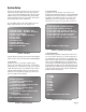
Advanced Input Assignment: Analog Input Name Change This set is available should you wish to rename any of the analog inputs. Press the number of the input you wish to rename then press the GUIDE button. A new menu on the OSD page will appear. This menu will show the default and actual name as well as five Xs. Use the cursor buttons to move up, down, left or right to select and change letters and/or numbers to create the new name. Press EXIT when done to return to the previous menu. 4.
0. Reset to Defaults We recommend not using this feature unless there is trouble with any of the settings you have made. This is a quick way to return the unit to “out of box” conditions. This will also be used when there are updates to the firmware. Press “0” on the remote when in the main menu. You can toggle between “NO” and “YES” by using the SELECT button. Please exercise extreme caution. CAUTION: USE EXTREME CAUTION WHEN USING THIS FEATURE AS IT COULD RETURN ALL YOUR SETTINGS TO FACTORY DEFAULTS.
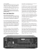
Typical Source Connections Here is a typical source connection for the ATP7500. It is shown only as an example and is by no means mandatory. There are endless possibilities regarding what and how you can connect to the rear panel.
5.
6.
7.
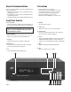
Remote Control Operation The remote control is preprogrammed to operate the ATP7500 Digital Preamplifier-Processor in the AVC mode. It also has 7 other Device modes (accessed via the top two rows of buttons) including CD (CD player), DVD (DVD Player), AUX (auxillary), SAT (satellite), TV (television), VCR (videocassette recorder) and CBL (cable box) for learning functions from the remote controls of other equipment from other manufacturers.
MENU When you press this key, the ATP7500 goes to setup mode. Use the up/down/left/right keys to navigate the menus. The ATP7500 escapes from setup mode when you either select EXIT from the OSD or press the MENU key again. EXIT This key exits the setup mode without saving the new settings. Use it if you have adjusted the setup menu by accident. SELECT/PLAY This is the enter key in setup mode. You can us it to access sub-menus or to activate special menu items.
Remote Control Programming The remote allows you to transfer a command from a button on your source remote control (original equipment remote control) to a button on the ATP7500 remote control. In the CD, DVD, AUX, SAT, TV,VCR and CBL device modes, new commands can be taught to any button except the LIGHT button. The remote control provides distinct visual feedback with LEDs (Light Emitting Diodes) that are located at the top left of the remote control (Status LED) and under the Device buttons.
To Erase a Learned Command From a Button Step 1. Press the Device button and SELECT buttons simultaneously, and hold until the orange Status LED and the Device button turn on and remain lit. Step 2. On the remote control, press the button that is to be erased. The orange Status LED will flash continuously and the Device button will turn off. Step 3. Press the LIGHT button. The green status LED will flash twice, then turn to a steady orange. The Device button will turn on.
Programming the Macro Buttons Macro buttons (M1, M2, M3, M4 and POWER) can send out a sequence of up to ten (10) commands with one button press. Macros can be programmed in both the AVC and SAT modes but can also be accessed in other modes. If a macro is programmed in the AVC mode, that macro can also be accessed in the CD, DVD, and AUX modes. If a macro is programmed in the SAT mode, that macro can also be accessed in the TV, VCR and CBL modes.
Replacing the AC Power Fuse ATI Service Information 1. Turn the unit off. 2. Disconnect the AC power cord. 3. Slide open the fuse drawer completely. 4. Remove and replace the fuse in the rear compartment. 5. Close fuse drawer completely. 6. Reconnect the AC power cord. Note: Use fuse type 5 x 20 mm 1.0 Amp fast blow (IEC 127F). In the event that the unit must be returned to the factory, an RMA (Returned Merchandise Authorization) number must be requested from Amplifier Technologies, Inc.
Specifications All Specifications refer to 1 Vrms and 0 dBf digital or 2 Vrms analog input, except when stated. Input Level Output Level (Preamp) Input Impedance 200mVrms 3.5 Vrms 15 k Ohms Total Harmonic Distortion (Stereo Source) <0.03% Total Harmonic Distortion (7.1 Channel Source) 0.003% Frequency Response (Stereo Bypass Mode) Stereo Analog Input Level Signal-to-Noise Ratio 20Hz to 20kHz (±0.
90-Day Limited Warranty Terms and Conditions (7-Year Optional Extended Warranty) This ATI product is warranted against defects in materials and workmanship for 90 days from the date of purchase by the original owner. The date of purchase shall be established by the original owner presenting to the ATI Customer Service Facility the original owner’s purchase receipt or sales slip showing from whom the product was purchased, the date of purchase and the purchase price of the unit.
Amplifier Technologies, Inc. 19528 Ventura Boulevard #318 Tarzana, CA 91356 (818) 343-4777 Fax: (818) 343-7444 http://www.ati-amp.com EMAIL: sales@ati-amp.com Revision 1.