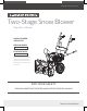
Save This Manual for Future Reference Two-Stage Snow Blower Operator’s Manual MODEL NUMBER 1005425196 SERIAL NUMBER PURCHASE DATE Both model number and serial number may be found on the main label. You should record both of them in a safe place for future use.
Your new LEGEND FORCE snow blower offers quality construction, and is easy and safe to operate. With proper use and care, it is designed to give you many years of dependable service.
Two-Stage Snow Blower » Operator’s Manual MODEL AND SERIAL NUMBERS Carefully read through this entire operator's manual before using your new unit. Pay attention to all cautions and warnings. This unit is a gasoline engine driven snow blower. It is perfect for tacking medium snowfall – easily able to cut through snow in excess of a foot or more. It is easy and safe to operate. With proper use and care, it should give you many years of dependable service.
SUPPORT Have questions about your LEGEND FORCE equipment? Call us at 1- 877-527-0313. SPECIFICATIONS Model Number 1005425196 Clearing Width 22" Engine Displacement 196 cc Start Type Recoil Auger Diameter 9.
Two-Stage Snow Blower » Operator’s Manual SYMBOLS The rating plate on your machine may show symbols. These represent important information about the product or instructions on its use. Read these instructions carefully. No smoking, sparks, or flames. Wear eye protection. Do not touch parts which are hot from operation. Serious burns may result. Wear hearing protection. Wear safety footwear. Stop engine, remove key, read manual before making any repairs or adjustments.
PERSONAL SAFETY Do not permit children to operate this machine at any time. Keep children, pets, and other people not using the unit away from the work area. Be alert and shut off unit if anyone enters work area. Keep children under the watchful care of a responsible adult. Do not operate the machine while under the influence of drugs, alcohol, or any medication that could affect your ability to use it properly. Dress properly. Wear heavy long pants, boots, and gloves.
Two-Stage Snow Blower Loosen the fuel tank cap slowly to relieve any pressure in the tank. » Operator’s Manual When fuel is spilled on yourself or your clothes, wash your skin and change clothes immediately. Never overfill the fuel tank. Fill the tank to no more than 1/2” below the bottom of the filler neck to provide space for expansion as the heat of the engine can cause fuel to expand. Store fuel in containers specifically designed and approved for this purpose.
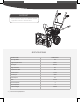
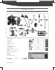
CONTENTS SUPPLIED Your Legend Force snow blower comes partially assembled and contains the following: 1 3 4 5 2 8 10 7 6 13 Premium 4-Cycle 14 HARDWARE KIT NET CONTENTS 20 OZ (0.6 L) 15 11 9 12 1. Main Machine 2. Control Panel 3. Handlebars 4. Shift Lever M6 X 40 X4 2 M6 X 30 X1 3 M6 X 30 X6 5. Chute Clean-Out Tool X3 6. Wheel M8 7. Directional Chute Control X1 X1 8. Discharge Chute 9. Chute Crank Flange M8 X 25 X2 10.
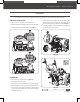
Two-Stage Snow Blower » Operator’s Manual ASSEMBLY This snow blower was partially assembled at the factory. To assemble your machine follow the below instructions. ENGINE AIR FILTER COVER 1. R emove wing nut and washer from the air filter cover. 2. Rotate the air filter cover by 180° so that the primer faces outside. 3. I nstall air filter cover and tighten wing nut. (See Figure 1) 5. A lign the holes in the handlebars with the upper holes on both sides of the transmission housing.
WHEELS SPEED SHIFT LINKAGE 1. R emove the axle pin from the axle. (See Figure 3 #1) 1. Remove the knob to slide the shift lever up and through the slot in the control panel. 2. S lide the wheel on the axle. (See Figure 3 #2) 3. Insert the axle pin through the hole in the wheel hub and through the inside hole in the axle. When inserting the pin into the wheel, place the hole side of the pin block towards the outside for easier installation. (See Figure 3 #3) 2.
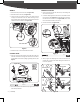
Two-Stage Snow Blower » Operator’s Manual CONTROL CABLES CHUTE CLEAN-OUT TOOL Disconnect the Z-fittings from the turnbuckles and hook them into the lower holes in the clutch levers. Thread the turnbuckles without turning the cables onto Z-fittings until there is no slack in the cables. Do not overtighten the cables. Hold the flats on the turnbuckles with pliers and tighten the jam nuts against the turnbuckles.
2. P lace the discharge chute facing it forward over the chute crank flange. (See Figure 8b) Two-person assembly is required. Please plan to assemble the discharge chute when another person can be available help to hold the discharge chute into its position. DIRECTIONAL CHUTE CONTROL 1. Slide the spiral end of the directional chute control lever into the chute bracket. 2.
Two-Stage Snow Blower » Operator’s Manual SKID SHOES TIRES 1. Place the machine on a solid, level surface. The tires are over-inflated at factory for shipping purposes. Check the pressure in the tires prior to usage. Reduce or increase air pressure to ensure equal tire pressure to the manufacturer’s recommended pressure. The recommended air pressure can be found on the tire sidewall. 2.
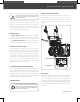
KNOW YOUR MACHINE FEATURES AND CONTROLS Shear Pin Auger Gearcase Auger Clutch Lever Scraper Blade Drive Clutch Lever Chute Deflector Speed Shift Lever Directional Chute Control Discharge Chute Belt Cover Chute Clean-Out Tool Skid Shoes Auger Fuel Filler Cap Primer Throttle Control Choke Control Fuel Shutoff Valve Recoil Starter Handle 13 | Know Your Machine Engine ON/OFF Switch Engine Oil Fill Cap w/ Dipstick
Two-Stage Snow Blower SPEED SHIFT LEVER The speed shift lever has 7 positions: 5 forward speeds and 2 reverse. To change speeds, move the speed shift lever to the desired position. The lever locks in a notch at each speed selection. Always release the drive clutch lever before changing speeds. Failure to do so will result in damage to the snow blower. Slower speeds are for heavier snow and faster speeds are for light snow and transporting the snow blower.
3. Grasp the tool firmly by the handle and push and twist the tool into the discharge chute to dislodge the blockage. 4. R efasten the clean-out tool to the mounting clip on the rear of the auger housing. 5. M ake sure the discharge chute is pointed in a safe direction (no vehicles, buildings, people, or other objects are in the direction of discharge). Restart the engine.
Two-Stage Snow Blower » Operator’s Manual ADJUSTMENT SKID SHOES AUGER CLUTCH AND DRIVE CLUTCH Position the skid shoes based on surface conditions. For removal of snow in normal conditions, such as a paved driveway or sidewalk, place skid shoes in the higher position to give a 1/8” (3mm) clearance between the scraper blade and the ground. Use a middle or lower position when the area to be cleared is uneven.
To do so: 1. L oose the two nuts which secure the chute bracket and reposition it slightly. 2. Retighten the nuts.
Two-Stage Snow Blower » Operator’s Manual OPERATION FREEWHEELING AND SELF-PROPELLING Left wheel equipped with the axle lock pin can be completely released by removing the pin and installing it in the outer axle hole. Unlock the left wheel to allow for easier turning of the unit. To unlock the left wheel, remove the pin from the inner hole and insert the axle pin through the outer axle hole, but not through the wheel hub.
SNOW BLOWING TIPS TRAVELING It is easier and more efficient to remove snow immediately after it falls. To travel from one work area to another: The best time to remove snow is the early morning. At this time the snow is usually dry and has not been exposed to the direct sun and warming temperatures. Slightly overlap each successive path to ensure all snow will be removed. 1. Set throttle to slow or part-throttle position. 2.
Two-Stage Snow Blower » Operator’s Manual MAINTENANCE ENGINE Refer to the Engine Operator’s Manual. AUGER GEARBOX The gearbox was filled with lubricant to the proper level at the factory. Unless there is evidence of leakage or service has been performed on the gearbox, no additional lubricant should be required. If lubricant is required, use GL-5 or GL-6, SAE85-95, EP gear oil lubricant. Do not use synthetic oil. Oil Grease Do not allow grease or oil get on friction disc, friction plate or belts.
SERVICE REPLACEMENT SHEAR PINS AUGER BELT REPLACEMENT A pair of replacement auger shear pins and clevis pins are included with your snow blower. Store them in a safe place until needed. If the auger belt becomes worn, oil-soaked, or otherwise damaged, proceed as follows to replace the belt. 1. T o prevent spillage, remove all fuel from tank by running engine until it stops. Remove the key to avoid unintended starting and allow unit to cool completely. 2.
Two-Stage Snow Blower » Operator’s Manual 4. C arefully pivot the snow blower up and forward so that it rests on the auger housing. 2. R emove the two screws that hold the belt cover in place and set the cover aside. (See Figure 20a) 5. R emove the frame cover from the underside of the snow blower by removing the screws which secure the cover. (See Figure 20c) 3. Remove the belt as follows. a. Roll the auger belt off the engine pulley. (See Figure 20b) b.
7. R emove and replace belt in the reverse order. FRICTION WHEEL REPLACEMENT Holding down the drive clutch lever will ease reinstallation of the belt. If the snow blower fails to drive with the drive clutch engaged, and performing the clutch control cable adjustment fails to correct the problem, the friction wheel may need to be replaced. If an assistant is available, you can also separate the auger housing from the frame assembly to replace belts. 1.
Two-Stage Snow Blower 6. R emove the other bearing from the left side of the frame by removing the snap ring. » Operator’s Manual 8. Follow the previous steps in reverse order to reassemble. If you only want to replace the rubber ring, proceed as follows: 1. R emove the six screws which secure the friction wheel’s side plates together. (See Figure 22e) Rubber Ring Bearing 10 mm Snap Ring Figure 22c Figure 22e 7.
TROUBLESHOOTING Problem Cause Remedy 1. Move choke to CHOKE position 1. Choke not in CHOKE position 2. Engine not primed 3. Engine is flooded 4. Fuel shut-off valve closed 5. T hrottle in STOP position or RUN/ STOP switch is STOP Engine fails to start 6. S park plug wire loose or disconnected 7. Fuel tank empty or stale fuel Engine Leakage 2. P rime engine as instructed in this manual 3. W ait a few minutes before restarting, do not prime 4. Open fuel shut-off valve 5.
Two-Stage Snow Blower Problem Loss of power Loss of traction drive Cause 1. T ighten spark plug wire 2. G as cap vent hole plugged 2. C lean or replace fuel cap 3. D irty or clogged muffler 3. C lean or replace muffler 1. D rive control cable not adjusted properly 1. A djust drive control cable 2. D rive belt loose or damaged 1. D ischarge chute clogged 2. A ugers or impeller jammed 3. A uger control cable not adjusted properly 4. A uger belt loose or damaged 5.
PARTS DIAGRAM 27 | Parts Diagram
Two-Stage Snow Blower » Operator’s Manual Parts Diagram | 28
PARTS LIST No. Description QTY No. Description QTY No. Description QTY 1 Spiral Assembly R 1 36 Bolt M8x20 6 71 Tension Pulley Plate 1 2 Washer 2 37 Bolt M8x25 2 72 Bolt M8x40 1 3 Big Washer 2 38 Plug 1 73 Plastic Sleeve 2 4 Sealing B20x35x7 3 39 Auger Housing Assy. 1 74 Oscillating Bar 1 5 Bolt 8.
Two-Stage Snow Blower No. Description QTY No. Description QTY No. » Operator’s Manual Description QTY 106 Screw M8x16 14 123 Nut M6 5 140 Left Handle Pipe 1 107 Cable Roller 1 124 Washer 10 6 141 Drive Clutch Cable 1 108 Roller Bushing 3 125 Supporting Plate 1 142 Gear Shift Board 1 109 FT Bolt M6x25 2 126 Bushing 1 143 Bolt 8.
1- 877-527-0313