
Use and Care Manual

1
3
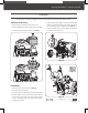
Adjusting Bolt
2
Upper Hole
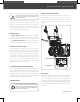
SPEED SHIFT LINKAGE
CONTROL PANEL
1. Remove the knob to slide the shift lever up and through the
slot in the control panel.
2. Loosen the adjusting bolt on the shift arm, then slide the shift
lever into place. (See Figure 5a) Use the bolt and nut to secure
the shift lever to the shift arm. (See Figure 5a #2) Secure shift
lever to the shift arm with screw and nut.
3. Reattach the knob. (See Figure 5a #3)
4. Slowly tighten the adjusting bolt until the shift lever has
tension with a spring action when shifting from Neutral to a
Drive Gear position.
M6 X 40 X 4
2
M6 X 30 X 1
3
16
mm
10
mm
5
mm
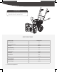
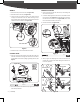
2. Once control panel is installed. Securely tighten lower handle
and control panel bolts.
1. Place the control panel between the handle bars. Slide the
four bolts and washers through the two holes on each side of
the handlebar. Secure them by nger tightening the nuts. (See
Figure 4).
16
mm
10
mm
X 2
21
43
Neutral Position
Adjusting Bolt
Jam Nut
Drive Gear
Position
Neutral
Position
9
|
Assembly
Figure 5a
Figure 4
Figure 5b
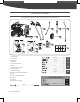
WHEELS
1. Remove the axle pin from the axle. (See Figure 3 #1)
2. Slide the wheel on the axle. (See Figure 3 #2)
3. Insert the axle pin through the hole in the wheel hub and
through the inside hole in the axle. When inserting the pin
into the wheel, place the hole side of the pin block towards the
outside for easier installation. (See Figure 3 #3)
4. Follow the steps 1-3 to assemble the other wheel.
Inside Hole
1
2
3
Figure 3