
Installation Instructions

No: 340974 – 10/14
© Copyright 2012 Legrand All Rights Reserved.
60 Woodlawn Street
West Hartford, CT 06110
1.877.BY.LEGRAND
(295.3472)
www.legrand.us
570 Applewood Crescent
Vaughan, ONT L4K 4B4
905.738.9195
www.legrand.ca
1-POLE
3-WAY
WHITE
HOT
AY
AY
W
W
1-POLE
STRIP
3-WAY
WHITE
HOT
P
W
W
3
3
The ASOS32 is designed to replace a standard single pole or multi-way light or
fan switch. The sensor uses passive infrared technology to sense human motion
in a space and turn the lights or fan ON when occupancy is detected and OFF
when the room is vacant. It is ideal for applications in a home where there is a
direct line of sight from the sensor to the room.
Upon detection of occupancy the sensor will turn the light or fan (controlled
load) ON. The sensor will keep the controlled load on until no motion is detected
for the selected time delay. If the controlled load is turned off manually (e.g. to
keep the lights off while watching a movie) the sensor will keep the connected
load off as long as it is detecting motion. The sensor will automatically switch
back to automatic-on when no motion is detected for 5 minutes.
LED functionality
The occupancy sensor has one locator LED on the ON/OFF button. When the
connected load is off the locator LED will be on. When the connected load
is on the locator LED will be off.
Note: The LEDs will only function when the neutral wire is connected.
When the neutral wire is not connected the device will function properly,
but the locator LED will never be illuminated. See Step 4 above for details
on how to wire the device.
Initial Power Up Supply
There is an initial warm-up and calibration period the first time power is applied
to the units, after a power failure lasting more than 5 minutes and after the load
is replaced.
SENSOR ADJUSTMENT & PROGRAMMING
Adjusting the time delay
The factory setting for the time delay dial is 15 minutes. To increase the
amount of time the load remains ON after the last motion detection, turn the
dial clockwise (maximum = 30 minutes). To reduce the amount of time the
load remains ON after the last motion detection, turn the dial counterclockwise
(minimum = 30 seconds). The unit will enter test mode if the trimpot is turned
fully counter-clockwise. Stop just before turning the trimpot completely counter-
clockwise to avoid entering test mode. See Test Mode section for further details.
Adjusting the light level
Adjust the light level setting to prevent the sensor from automatically turning
on the lights when there is enough ambient light present in the space. This
feature’s default setting is maximum so that even the brightest light will not pre-
vent the sensor from turning the connected load on when it detects occupancy.
Follow these steps to set the light level:
• The light level must be set when the lights would normally be turned off
because there is enough ambient light
• Wait until the time of day when the space is bright enough with the ambient
light and does not need additional electric light
• Flip the dip switch labeled “light level” to the on position
• Any time the ambient light gets to the current level or brighter the sensor will
not turn the lights on automatically
• To disable this feature, turn the “light level” dip switch to the off position
Disabling the locator LED
The locator LED can be disabled by pressing and holding the on/off button for
10 seconds. After 10 seconds the locator LED will flash to indicate that the loca-
tor LED has been disabled. To enable the LED, press and hold the on/off but-
ton for 12 seconds. The locator LED will flash at 10 seconds, continue to keep
holding down the on/off button until the locator LED flashes twice at 12 seconds
indicating that the LED has been enabled.
Test Mode
Activate test mode in order to test the detection coverage. If the neutral wire
is connected, the locator LED will blink indicating that the unit is in test mode.
During test mode the controlled load turns on for 5 seconds each time the sen-
sor detects occupancy. Follow these steps:
• Turn the time delay trimpot fully counter-clockwise
• Move out of the coverage area or stand very still. The controlled load turns off
after 5 seconds if no motion is detected
• Move into the coverage area. The controlled load turns on for 5 seconds
each time the sensor detects motion. After 5 seconds expires without motion
detection, the load turns OFF. The controlled load turns on automatically with
the next motion detection and stays on for 5 seconds
• Repeat as necessary to ensure that the desired coverage areas are within
detection range
• The device will remain in test mode for 5 minutes before automatically revert-
ing back to normal operation. Once the device is in normal operating mode,
the time delay will be set to 5 minutes. If additional time is needed, turn the
trimpot away from the minimum setting, and then turn back to its minimum
setting, resetting the 5 minutes.
• Turn the trimpot back to the desired time delay once the coverage area has
been verified
TROUBLESHOOTING
Status LED is enabled but and the load will not turn ON:
• Check the lamp to make sure that it has not burned out
• Check the circuit breaker to be sure it is functioning
No Status LED:
• Check the ground and neutral connections (note: neutral is not
required for product to function properly)
Load will not turn ON:
• Press the ON/OFF button. The load should turn ON.
• When power is applied, there is up to a 20 second delay before the device
is operational. Wait 20 seconds and try again to turn on the load.
• Check the light bulb and/or motor switch on the fan mechanism
• Turn off power to the circuit then check wire connections
Load will not turn OFF:
• Make sure there is a solid ground connection. The device requires the ground
connection to operate
• Note: The time delay can be set from 30 seconds to 30 minutes. Ensure that
the time delay is set to the desired delay and that there is no movement within
the sensor’s view for that time period.
• To quickly test the unit for proper operation, turn the time delay to minimum
and move out of the sensor’s view. Lights should turn off after 5 seconds.
• Press the ON/OFF button. If load does not turn off, turn off power to the
circuit then check wire connections.
Factory reset
To change the operating mode back to the default settings press and hold the
on/off button for 15 seconds. The locator LED will flash once at 10 seconds,
continue to press and hold the on/off button. The locator LED will flash twice at
12 seconds, continue to press and hold the on/off button. The locator LED will
flash 3 times at 15 seconds signaling that the device has been reset.
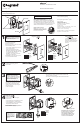
TOP
NOTE – If you need to
remove sensor after
snapping into frame, first
remove frame from wall
box to access the four
locking tabs on the back
of the sensor. Insert a flat
screwdriver to depress
tabs as you apply pressure
to push switch out.
NOTE – To remove wall
plate, insert a small, flat
screwdriver in notches on
wall plate and twist gently
to pry from frame.
4
5
Carefully fold wires
into box.
Snap sensor into
frame.
6
STRIP
GAGE
AY
WA
A
WA
W
WA
3-WAY
-W
3-W
3
-
-
3-W
3
3
3
3
3
3
3
WHITE
1
2
3
4
Snap wall plate to frame.
There are three click-
stops to adjust the fit
of the wall plate to the
sensor and the wall.
Never apply cleaner
directly to the sensor
or wall plate. Apply to a
soft cloth and use cloth
to remove any smudges
from the product.
Technical Assistance:
(877) 295-3472
www.adornemyhome.com/install
LIMITED LIFETIME WARRANTY
Limited lifetime warranty information for adorne products is available at
www.adornemyhome.com/warranty. Limited warranty information for
adorne
TM
products may also be obtained free of charge by sending a written
request, along with your proof of purchase (including purchase date), to:
Legrand
Attn: adorne Customer Service/Warranty Department
50 Boyd Avenue
Syracuse, NY 13209
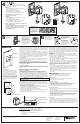
3-Way
The term master designates the sensor that connects
to the load. The term auxiliary refers to the sensor that
does not connect to the load.
Master
• Connect NEUTRAL wire from the circuit and from the
lamp (LOAD) to WHITE terminal
• Connect LINE wire to HOT terminal
• Connect LOAD wire to 1-POLE terminal
• Connect TRAVELER wire to the 3-WAY terminal
NOTE: NEUTRAL wire is not required for
sensor to function properly.
Auxiliary
• Connect NEUTRAL wire from circuit in the other wiring
box to WHITE terminal
• Connect LINE wire to HOT terminal
• Connect TRAVELER wire to the 3-WAY terminal
• 1-POLE terminal on auxiliary is not used
NOTES: A light can be controlled by one master and up
to four auxiliary sensors.
If you are installing multiple sensors in the frame, wire
all devices before snapping them into the frame.
Lens
On/Off Button
OPERATION
1-POLE
3-WAY
WHITE
HOT
AY
AY
W
W
1-POLE
STRIP
3-WAY
WHITE
HOT
P
W
W
3
3
3-Way Master
3-Way Auxiliary
1-POLE
STRIP GAGE
3-WAY WHITE
HOT
1-POLE
STRIP GAGE
3-WAY WHITE
HOT
1-POLE
STRIP GAGE
3-WAY WHITE
HOT
1-POLE
STRIP GAGE
3-WAY WHITE
HOT
Locator LED
Coverage Area
The ASOS32 has a maximum coverage
range of 180 degrees and a coverage
area of 600 sq. ft. The sensor must have
a clear and unobstructed view of the
coverage area. Objects blocking the sen-
sor’s lens may prevent detection thereby
causing the light to turn off even though
someone is in the area. Windows, glass
doors, and other transparent barriers will
obstruct the sensor’s view and prevent
detection.
CAUTION Do not overturn the time delay adjustment dial.
Major Motion 35’ (10.6 m)
Minor Motion 20’ (6 m)
7.5’ (2.2 m)
15’ (4.5 m)
TOP
Dip Switch Settings
Light Level Dip Switch
Time Delay Trimpot
Unused Dip Switch
WARNING: Do not
pair different size wires in
the same terminal. If you
have different size wires,
use a wire nut to add a 6
inch pigtail of the same
gauge wire to the smaller
gauge wire.
Same size. Different size.Different size
with pigtail.
Ground
Neutral
Hot/Line
Load
Traveler
Provides multi-way control only when used with
other ASOS32 devices.