MX535 UAIS Ship Borne Class A Transponder Unit Technical & Installation Manual WARNING: THIS EQUIPMENT COMPLIES WITH PART 80 OF THE FCC RULES. ANY CHANGES OR MODIFICATIONS NOT EXPRESSLY APPROVED BY THE MANUFACTURER COULD VOID THE USER’S AUTHORITY TO OPERATE THE EQUIPMENT. IMPORTANT NOTICE THE MX535 SYSTEM IS AN AID TO NAVIGATION. UNDER NO CIRCUMSTANCES SHOULD IT BE USED IN LIEU OF AUTHORIZED GOVERNMENT CHARTS.
Part No. 3508 102 70870 Rev. D MX-Marine January, 2005 By: TCD This document is the property of MX-Marine. It must not be reproduced or otherwise made available to any third party without our permission in writing. Alterations due to technical progress are reserved. MX Marine (USA) 23868 Hawthorne Blvd.
How To Contact Us? Contact your local MX-Marine, Leica dealer for: • Installation, Service, & Technical Support • Sales of Accessories • Hardware and Software Upgrades Unlike many other consumer electronics industries which only sell consumer electronic devices, your marine dealer is often your best advisor for installation and service of your new AIS unit. MX-Marine, Leica strongly encourages you to utilize the knowledge and experience of your sales and service dealer.
Table of Contents 1 1.1 1.2 1.3 2 2.1 2.2 2.3 2.4 3 General .............................................................................................................................................1 Software Releases ........................................................................................................................1 General Recommendations for Installation, Maintenance and Repair Work .........................1 Safety Warnings ....................................................
4 4.1 5 5.1 5.2 5.3 5.3.1 5.4 6 6.1 6.1.1 Technical Data ............................................................................................................................25 Technical Information ................................................................................................................25 Setting-to-Work/Configuration .............................................................................................27 Setting-to-Work .............................................
List of Abbreviations This list also contains abbreviations which are not used in this manual but in additional documentation.
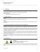
MX535 AIS Transponder Unit Technical & Installation Manual ____________________________________________________________________________________________ 1 General This Technical & Installation Manual is the installation manual for the MX535 AIS Transponder. It also contains information about the antennas (GPS and VHF) and cabling used by the MX535. Related Documents MX420 Operator’s Manual (P/N 3508 102 70040) 1.1 Software Releases MX535 This manual is valid for all software versions of the MX535.
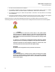
MX535 UAIS Transponder Unit Technical & Installation Manual _______________________________________________________________________________________ 1. The mat must be positioned at the workplace. 2. The potential equalization cable must be connected to the snap fastener and the clamp to a suitable protective earth contact. The cable contains a 1 MΩ resistor, which must not be removed. 3. The wristband must be put on.
MX535 AIS Transponder Unit Technical & Installation Manual ____________________________________________________________________________________________ 2 Overview The MX535 is an AIS Transponder Unit, which receives data from other vessels by means of a VHF radio and sends these data to the MX420 Control and Display Unit (CDU) or the ECDIS. In the opposite direction, the AIS receives data from the external GPS system and the ship’s sensors and transmit these data by means of the VHF radio.
MX535 UAIS Transponder Unit Technical & Installation Manual ____________________________________________________________________________________________ 2.3 UAIS MX535 with MX420/AIS or MKD CDU GPS ANT. MX-MARINE SMART DGPS ANTENNA (NOT USED FOR MKD). JB-50 Junction Box (optional) VHF ANT. MX535 TRANSPONDER MX420/AIS OR MX420/MKD EXT. GPS CH 4 MX420/MX535 communication CH 1 CH 3 CH 8 CH 5 CH 9 Ch2 (GLL,DTM,VTG) Non-MX535 ECDIS/ARPA Listener GYRO ROT LONG RANGE RTCM SC 104 unit Figure 2.
MX535 UAIS Transponder Unit Technical & Installation Manual ____________________________________________________________________________________________ 2.4 MX535 Transponder Overview Figure 2.2 – MX535 UAIS Transponder The aluminum housing shown in Fig. 2.2 contains a single Transponder Unit, which consists of the: Controller Interfaces VHF transmitter VHF receivers GPS receiver.
MX535 UAIS Transponder Unit Technical & Installation Manual ____________________________________________________________________________________________ 3 Installation . 3.1 General Requirements Please note that international conventions, regulations, instructions and guidelines have to be adhered to when installing the MX535 AIS transponder. The following points must be observed before installation can commence: • • • • • • Trained service personnel must undertake the installation.
MX535 UAIS Transponder Unit Technical & Installation Manual ___________________________________________________________________________________________________________________ 3.2.3 MX535 Connection Diagram MX-MARINE SMART DGPS ANTENNA (NOT USED FOR MKD). MX420/AIS OR MX420/MKD EXT. GPS Non-MX535 ECDIS/ARPA Listener MX420/MX535 communication Figure 2.3 – MX535 Connection Diagram Note: The MX535 JB-50 Junction Box (optional) includes a fuse of 6.3A.
MX535 UAIS Transponder Unit Technical & Installation Manual ___________________________________________________________________________________________________________________ GPS ANT. MX-MARINE SMART DGPS ANTENNA (NOT USED FOR MKD). JB-50 Junction Box (optional) VHF ANT. MX535 TRANSPONDER MX420/AIS OR MX420/MKD EXT. GPS CH 4 MX420/MX535 communication CH 1 CH 3 CH 8 CH 5 CH 9 Ch2 (GLL,DTM,VTG) Non-MX535 ECDIS/ARPA Listener GYRO ROT LONG RANGE RTCM SC 104 unit Figure 2.
MX535 UAIS Transponder Unit Technical & Installation Manual ___________________________________________________________________________________________________________________ 3.3.2 Interface NMEA Description 3.3.2.1 External Sensors - Interface on CH1, CH2, CH3 The MX535 AIS transponder requires connection to various sensor devices. MX535(AIS) and MX420/AIS or MKD (CDU) together offer the following configuration options: • • • • Set up data speed 4800 or 38400 baud.
MX535 UAIS Transponder Unit Technical & Installation Manual ___________________________________________________________________________________________________________________ 3.3.2.3 PILOT Port CH 5 The used sentence formatters for the pilot plug are the same as those listed for the ECDIS port (CH 4). Note: A pilot input/output port is part of an AIS Class A installation.
MX535 UAIS Transponder Unit Technical & Installation Manual ___________________________________________________________________________________________________________________ 3.3.2.5 DGPS – DGNSS Channel 9 Field / Protocol information: All fields are provided for further information; please refer to ITU-R M.823-2 / RTCM SC 104 for detailed field information. 3.3.2.
MX535 UAIS Transponder Unit Technical & Installation Manual ___________________________________________________________________________________________________________________ 3.4.1 Sensor Notes External Sensor The AIS has interfaces (configurable as IEC 61162-1 or 61162-2) for position, bottom track (BT) speed, heading and rate of turn (ROT) sensors. In general, sensors installed in compliance with other carriage requirements of SOLAS Chapter V should be connected to the AIS System.*1.
MX535 UAIS Transponder Unit Technical & Installation Manual ___________________________________________________________________________________________________________________ 3.4.2 Sensor Hardware Installation Installation of an RS422 serial interface: In most cases, the output from a GPS is already being used by existing navigation equipment. It is possible to split an RS-422 output for two devices. If the signal becomes too low, then an NMEA splitter has to be used.
MX535 UAIS Transponder Unit Technical & Installation Manual ___________________________________________________________________________________________________________________ 3.4.3 Priority Handling of Sensor Sentence The following table shows the priority handling of NMEA sentences. The sentences, which are treated with higher priority, are listed first.
MX535 UAIS Transponder Unit Technical & Installation Manual ___________________________________________________________________________________________________________________ GGA - Positioning System Fix Data Time, Position and fix related data form GPS receiver. 11 1 2 3 4 5 6 7 8 9 10 | 12 13 14 15 | | | | | | | | | | | | | | | $--GGA,hhmmss.ss,llll.ll,a,yyyyy.yy,a,x,xx,x.x,x.x,M,x.x,M,x.
MX535 UAIS Transponder Unit Technical & Installation Manual ___________________________________________________________________________________________________________________ GNS - Fix Data 1 2 3 4 5 6 7 8 9 10 11 12 13 | | | | | | | | | | | | | $--GNS,hhmmss.ss,llll.ll,a,yyyyy.yy,a,c--c,xx,x.x,x.x,x.x,x.x,x.
MX535 UAIS Transponder Unit Technical & Installation Manual ___________________________________________________________________________________________________________________ VBW - Ground/Water Speed 1 2 3 4 5 6 7 | | | | | | | $--VBW,x.x,x.x,A,x.x,x.x,A*hh Field Numbers: Used Fields: 1,5,6,7,8,9 1:COG 5:SOG 6:SOGIn 7:SOG 8:SOGIn 9:Valid OSD - Ship Data 1 2 3 4 5 6 7 8 9 10 | | | | | | | | | | $--OSD,x.x,A,x.x,a,x.x,a,x.x,x.
MX535 UAIS Transponder Unit Technical & Installation Manual ___________________________________________________________________________________________________________________ Used Fields: 1,2 1:ROT 2:Valid Versions of NMEA Sentences RMC v2.30 - $GPRMC,122500.00,A,5330.1234,N,01001.2345,E,11.2,352.2,120202,2.0,E,A v2.20 - $GPRMC,122500.00,A,5330.1234,N,01001.2345,E,11.2,352.2,120202,2.0,E GLL v2.30 - $GPGLL,5330.1234,N,01001.2345,E,141800.00,A,A v2.00 - $GPGLL,5330.1234,N,01001.2345,E,141800.00,A v1.
MX535 UAIS Transponder Unit Technical & Installation Manual ___________________________________________________________________________________________________________________ 3.4.
MX535 UAIS Transponder Unit Technical & Installation Manual ___________________________________________________________________________________________________________________ Pin-Description AIS-Connector: AIS -Cable Sub-D 50 Plug Note: TxA TxB RxA RxB out – out + in – in + 16 17 33 48 49 32 + 24 VDC/max 5A + 24 VDC + 24 VDC 0 V 0 V 0 V rd rd rd bl bl bl DGPS Long Range Pilot Port MX420/AIS or MKD Channel 1,2,3 AIS-Cable Open CH1_in+ CH1_inCH1_gnd CH2_gnd CH2_in+ CH2_inCH3_in+ CH3_inCH3_gnd CH4_
MX535 UAIS Transponder Unit Technical & Installation Manual ___________________________________________________________________________________________________________________ 3.5 Installation of VHF / GPS Antennas Interference to the Ship’s VHF Radiotelephone The AIS ship borne equipment, like any other ship borne transceiver operating in the VHF maritime band, may cause interference to a ship’s VHF radiotelephone. Because AIS is a digital system, this interference may occur as a periodic (e.g.
MX535 UAIS Transponder Unit Technical & Installation Manual ___________________________________________________________________________________________________________________ 3.5.2 GNSS Antenna Installation Antenna Location The GNSS antenna must be installed where it has a clear view of the sky, so that it accesses the horizon freely through 360°, with a vertical observation of 5 to 90 degrees above the horizon.
MX535 UAIS Transponder Unit Technical & Installation Manual ___________________________________________________________________________________________________________________ 3.6 Specific Recommendations 3.6.1 Recommendations Concerning AIS Systems Recommendations for the installation of AIS systems are published in the IMO document NAV 48/WP.1. See this document for further information. The following sections also contain information, which has been taken from IMO NAV 48/WP.1. 3.6.
MX535 UAIS Transponder Unit Technical & Installation Manual ___________________________________________________________________________________________________________________ 3.6.5 Recommendations Concerning Redundancy If possible, the Transponder Unit should be supplied with the ship’s Position sensor data from two different sources, e.g. MX521 Smart DGPS antenna or the MX525 DGPS Sensor or other equivalent sensors). 3.6.
MX535 UAIS Transponder Unit Technical & Installation Manual ____________________________________________________________________________________________ 4 Technical Data 4.1 Technical Information PHYSICAL Size in mm / inch (w) Size in mm / inch (h) Size in mm / inch (d) Weight Operating Temperature 201.26mm / 7.92inch 60mm / 2.36inch 281.26mm / 11.07inch 2490g / 5.50lb -15°C to +55°C / 5°F to 131°F POWER SUPPLY Supply Voltage (galvanic isolated) Input Current 24 V DC (-10% +30%) min.
MX535 UAIS Transponder Unit Technical & Installation Manual ____________________________________________________________________________________________ BUILT IN GPS Receiver Architecture Tracking Capability Accuracy Horizontal Accuracy Vertical GPS Antenna Connector DGPS Accuracy *) depends on SA 12 channel differential 12 satellites sim.
MX535 UAIS Transponder Unit Technical & Installation Manual ____________________________________________________________________________________________ 5 Setting-to-Work/Configuration 5.1 Setting-to-Work The AIS Transponder Unit and antennas must be installed as described in Section 3.2.2, Page 6 (Step-by-Step Installation Procedure). For information about the dimensions see Section 4.2 (Technical Information).
MX535 UAIS Transponder Unit Technical & Installation Manual ____________________________________________________________________________________________ 5.4 Testing The Transponder Unit has neither traffic light indicators nor a display. Correct functioning cannot be made visible directly. To test the interfaces of the ship’s sensor inputs and the interface to the display unit, set the system in operation and view the own ship’s (AIS1 Screen) data in the MKD.
MX535 UAIS Transponder Unit Technical & Installation Manual ____________________________________________________________________________________________ MX535 PORT CONNECTIONS MX420/AIS or MKD MX535 TRANSPONDER CHANNEL 4 Cable B (NMEA 5) 8 NMEA5 IN (A) 8 OUT - 9 NMEA5 IN (B) 7 OUT + 10 NMEA5 OUT (A) 6 IN - 11 NMEA5 OUT (B) 5 IN + CHANNEL 2 Cable C (NMEA 8) 16 NMEA8 OUT (A) 17 NMEA8 OUT (B) 2 IN - 1 IN + Figure 2.5 - Cable connection for the MX535 AIS to MX420/MKD 3.
MX535 UAIS Transponder Unit Technical & Installation Manual ____________________________________________________________________________________________ Status messages of the connected sensors, sent when requested Position report Another message received Alarm: External position data not available Alarm: Heading data not avail able !AIVDO,2,2,0,B,00000000000,2*25 !AIVDO,1,1,,,139K6D7037H@L7FBOLDCr39R0000,0*3D !AIVDO,1,1,,A,139K6D7037H@L7FBOLDCr39R08AM,0*78 !AIVDO,1,1,,,139K6D7037H@L9:BOLBCr39T0000,0*
MX535 UAIS Transponder Unit Technical & Installation Manual ____________________________________________________________________________________________ 7 Fault Code List The following fault codes (integrity alarm conditions) can be displayed at the MKD (AIS9 Screen).
MX535 UAIS Transponder Unit Technical & Installation Manual ____________________________________________________________________________________________ 029 030 032 AIS: No valid SOG information Reaction: The Transponder Unit continues operation. No data from Remedy: external sensor The telegrams VBW, VTG, RMC can not be received.
MX535 UAIS Transponder Unit Technical & Installation Manual ____________________________________________________________________________________________ 8 Cabling Documents Grounding Grounding connection is important for EMC purposes as well as for protecting people’s lives. Regardless of the type of ship’s grounding (e.g. star pattern or ground plane pattern), no potential difference should be measurable between two different ground connectors.
MX 422 Prof ession al DG PS N avigat or MX 420/AIS Connector (C) (18-Pin) Cable C Cable B Connector (B) (18-Pin) Cable A [NMEA3 / GPS Out (A)] [NMEA3 / GPS Out (B)] [NMEA2 In (A)] [NMEA2 In (B)] [NMEA2 Out (A)] [NMEA2 Out (B)] [Pwr In (-)] [ ALARM Out] [Digital In 2] [Digital In 1] [NMEA4 / Beacon In (A)] [NMEA4 / Beacon In (B)] [NMEA6 In (A)] [NMEA6 In (B)] [NMEA6 Out (A)] [NMEA6 Out (B)] [1 PPS +] [1PPS -] WHT YEL BLK - + - + GRN GRN/WHT - +- + - + - + YEL YEL/BLK [NMEA10 Out (A)] [NMEA10
MX535 UAIS Transponder Unit Technical & Installation Manual ____________________________________________________________________________________________ Figure 2.7 – Dimensional Drawing for AIS Cable www.mx-marine.
MX535 UAIS Transponder Unit Technical & Installation Manual ____________________________________________________________________________________________ Figure 2.8 – Dimensional Drawing for Connection Box www.mx-marine.
MX535 UAIS Transponder Unit Technical & Installation Manual ____________________________________________________________________________________________ Figure 2.9 – Dimensional Drawing for GPS/VHF Cable www.mx-marine.
MX535 UAIS Transponder Unit Technical & Installation Manual ____________________________________________________________________________________________ Figure 3.0 – Dimensional Drawing for MX535 www.mx-marine.
MX535 UAIS Transponder Unit Technical & Installation Manual ____________________________________________________________________________________________ Figure 3.1 – Dimensional Drawing for MX535, opt. Mounting Kits www.mx-marine.
MX535 UAIS Transponder Unit Technical & Installation Manual ____________________________________________________________________________________________ PRODUCT WARRANTY AND LIMITATION OF LIABILITY This product is warranteed by MX-Marine (the “Seller”) to original purchaser (the “buyer”) for use only to be free of all defects in material and workmanship for a period of twelve (12) months from date of purchase by Buyer.
MX-Marine (USA) 23868 Hawthorne Blvd., Suite 201 Torrance, CA 90505 USA MX-Marine (UK) Ocean Quay Southampton SO14 5QY United Kingdom +1 310 791 8213 (Telephone) +1 310 791 6108 (Fax) +44(2380) 33 99 22 (Telephone) +44(2380) 33 03 45 (Fax) Internet: www.mx-marine.