Leica Rugby 410/420 DG User Manual Version 1.
Introduction Purchase Congratulations on the purchase of a Rugby instrument. This manual contains important safety directions as well as instructions for setting up the product and operating it. Refer to "9 Safety Directions" for further information. Read carefully through the User Manual before you switch on the product. Trademarks XBeePro is a registered trademark of Digi International. All other trademarks are the property of their respective owner.
Table of Contents 1 Introduction 4 2 Features and Functions 5 3 Operation 6 3.1 3.2 3.3 3.4 3.5 3.6 4 5 6 7 8 9 10 Entering Grade Identification of the Axes Slope - Percent of Grade Alignment of the Axes Precise Alignment of the Axes Axis Alignment Application 6 8 8 8 9 10 Setup 13 4.1 General Setup 4.2 Setup Options 4.3 Additional Setup Options 13 13 17 Checking Level Accuracy 18 5.1 Checking Level Accuracy 5.2 Adjusting Level Accuracy 18 19 Accessories 20 6.1 Batteries 6.
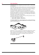
1 Introduction The Rugby Grade laser is designed to serve your needs in a wide variety of applications. It is a proven tool for increased production with substantial reduction of labor, time and material costs. It can be used to accurately control land leveling, sloped or level grading, trenching, open cut mining, dredging, contouring of levees, general construction and excavation. This manual contains operating and set-up procedures for common applications.
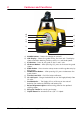
2 Features and Functions j) a) k) b) c) e) f) d) g) h) i) l) a) POWER Button – Powers the Rugby on and off. b) LCD Display – Shows the grade setting for the X axis. The display shows also Beam Masking, Battery status, H.I. and Head Speed. c) X/Y Button – Press to set grade in the X- and Y-axis. d) UP Arrow Button – After pressing X/Y, press to increase the grade shown. e) STAR Button – Press to enter setup screens and the grade entry by digit screen.
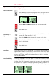
3 Operation 3.1 Entering Grade Direct Grade Entry Press POWER to turn the Rugby on. Press X/Y once to enter X-axis grade. Press X/Y again to enter Y-axis grade.The display will show the grade entry screens. Use the UP or DOWN buttons to set the desired grade. Press X/Y to exit. Grade Entry by Digit While in the grade entry screens, press the STAR button and a cursor will appear on the +/- sign. Press the STAR button to move the cursor to the right.
) If no button is pressed, the display will revert to the main display after ten seconds. Grade Swap The grade in the X and Y axes can easily be swapped from positive to negative in the Grade Entry by Digit screen. A typical application for this feature is road building. For example, with the Rugby setup on the crown of the road and with one axis aligned to the center line, the cross axis grade can be made to fall to the right or lefthand side simply by changing the +/- sign on the display.
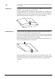
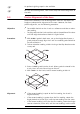
3.2 Identification of the Axes 1. X+ Axis – When positive grade is entered in the X-axis, grade will increase in this direction. 2. Y+ Axis – When positive grade is entered in the Y-axis, grade will increase in this direction. 3. Front of Rugby – See also axis labeling on the side of the laser and inside the top windows. 3.3 Slope - Percent of Grade Slope The change in elevation per unit of measure (foot, meter, etc.
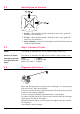
) ) 3.5 An optional sighting scope is also available. For very accurate alignment, refer to the steps for Precise Alignment of the Axes. Precise Alignment of the Axes Under most conditions, the raised alignment marks on the top of the Rugby are adequate for alignment of the axes. However, for more precise alignment, use the following procedure. Objective • To establish Point A on the Y-axis as a reference and take an elevation reading.
3.6 Axis Alignment Application The Axis Alignment Application is designed to precisely align the axis when grade accuracy is extremely important. For most applications, the traditional sighting method (using the sights on the laser, or using the optional sighting scope) is sufficient, but when precise grades are critical, it is important to have the axes accurately aligned. This Axis Alignment Application is only available on the Rugby 410/420 DG.
Step 2 • The X-Axis is automatically pre-selected as the axis to be precisely aligned. Press the X/Y button to change to the Y-axis if desired. During this process the cross-axis is automatically reset to 0.000% grade. • The cross axis is at 0.000% grade when 'OK' is shown on the display. • On the second control point adjust the Rod-Eye receiver on the grade rod and make sure it is located in the on-grade position on the axis selected (solid bar or solid tone). This part of step 2 is very important.
Step 4 Notes Important Limits and Exceptions 12 • Hold the receiver steady and watch the laser beam. When the ongrade signal is achieved, the laser is precisely aligned. • Press the STAR button to apply the axis correction, to quit the application and return to the main menu. • The X and Y-axis return now to the previously entered grade values. The alignment is electronically compensated; therefore the mechanical alignment of the laser may not be in alignment with the axes.
4 Setup 4.1 General Setup Location Make sure the location is clear of possible obstructions that may block or reflect the laser beam. Make the most efficient use of the Rugby’s operating radius. The Rugby can be placed in the center of the working area or to one side. Make sure the ground is stable. Ground vibration and extremely windy conditions can affect the operation of the Rugby. If working in very dusty conditions, place the Rugby up-wind.
HI Function – Turns the H.I. function on and off. Automatic, Manual or Manual with Grade. Wind Sensitivity (1-5) – (1) for calm days, (3) for normal days, (5) for extremely windy days. Beam Masking – Turns the beam off in the selected quadrants. Changing the Setup Options When entering the setup screen, the EXIT window will be highlighted.
H.I. (Height of Instrument) The H.I. function is used to prevent elevation changes caused by movement of the tripod. When the H.I. Alert function is activated, the self-leveling accuracy remains the same, but the self-leveling range of the Rugby is reduced. Movement of the Rugby beyond its self-leveling range will cause an “alert condition”.
Manual Mode with Grade In Manual Mode with Grade, the display will alternately show the grade entered for the X- and Y-axis and the crossed out level vial as shown here: In this mode, grade can be entered into either axis. The Rugby will selflevel to the grade input in the unit, then will lock into manual mode at this grade. ) Once locked in manual mode the self-leveling function is turned off.
4.3 Additional Setup Options Additional setup options may be accessed in a second setup screen. + From the main operating screen, Press and hold the UP button, then press the STAR button to access the second level setup screen. Selects beam masking at the diagonals or at the corners. Allows the Rugby to always start up with no beam masking, or to save and start up with the last beam mask setting used. Allows the Rugby to start up with the H.I. Alert automatically turned on, or turned off.
5 ) ) ) 5.1 Checking Level Accuracy It is the responsibility of the user to follow operating instructions, and to periodically check the accuracy of the instrument and work as it progresses. The Rugby is adjusted to the defined accuracy specification at the factory. It is recommended to check your laser for accuracy upon receipt and periodically thereafter to ensure accuracy is maintained.
Checking the Y-Axis Align the Y-axis by rotating the Rugby 90° so that the Y-axis is now square to the wall. Allow the unit to self-level completely, then check the Y-axis in the same way as above. 5.2 Adjusting Level Accuracy To Enter Adjustment Mode With the unit turned off, press and hold both the Up and Down buttons, then press the Power button to put the unit in adjustment mode. X-Axis Accuracy Adjustment If entered correctly, the X-axis adjustment screen will appear.
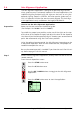
6 Accessories 6.1 Batteries The unique battery solution in the Rugby has two independent battery compartments that will accept various combinations of NiMH packs or individual D-cell batteries (2). The battery status is displayed on power-up and as small icons on the main operating screen. Install the NiMH batteries (1) as shown on the label of the pack. Install individual D-cell batteries (2) as shown on the battery door cover.
6.2 The Sighting Scope A sighting scope (739870) is available as an optional accessory for alignment of the axes and second day setups. The scope is magnetically mounted to the top of the housing and once aligned has a repeatable accuracy of approximately ± 0.2°. Alignment of the crosshairs If using the scope for reference or second day setup, use the raised sights on the top of the laser to align your Rugby to a second control point. The scope is roughly aligned at the factory.
6.3 Remote Control The Rugby LR Remote Control (765668) is a full functioning, twoway remote control. The LCD display and the grade and star buttons on the remote are the same as on the Rugby. The Power button turns on only the remote. When pressed it will communicate with the Rugby to receive current information. Once communication is established, the remote can be used to change grade and setup parameters on the laser.
Low Battery – The remote will display a low battery screen when the batteries have reached a voltage where the remote can no longer communicate with the laser. To replace the batteries, remove the bottom cover of the housing. Install as indicated on the side of the housing. Before you can use the remote it is necessary to enable the remote capability on the laser. To do this follow the instructions for entering and changing the setup in the second setup screen (page 17).
Remote Notes Setting the shut-off timer – The remote is set from the factory to shut off after two minutes of not being used. To change this shut-off time, enter the remote programming screen (just described) by pressing and holding the STAR button, then pressing the POWER button. When the Rugby select screen is shown, press and hold the STAND-BY button for 1.5 seconds. The shut-off time will change between 120, 60, or 30 seconds each time the button is held.
7 Troubleshooting 7.1 Display Screen Explanations Leica Start-up Screen • Can be programmed to display customer’s name and address. Battery Status Screen • Displays on power-up • Displays also when batteries are empty. Automatic Mode • Main Display Screen • Unit automatically self-levels. Manual Mode • Unit will not self-level • Grade can be changed with the grade/arrow buttons. Manual Mode with Grade • Unit will self-level to grades input, then lock in manual mode.
Negative Grade Disabled • The ability to enter negative grade has been disabled in the second setup screen. Grade greater than 15% • If attempting to enter grades greater than 15%, the cross axis grade is limited to 1%. • Four similar screens are possible. Lost Communication • The remote is out of range. Move closer. • 26 The remote is not in the line if sight of the laser.
7.2 Troubleshooting Suggestions Whenever there are questions regarding your laser, check the basics first. • Mode of operation - automatic, manual, manual with grade. • Battery status • Warning Screens - H.I., servo limit, temperature, adjustment. • Head speed setting • Beam mask setting Symptom Possible Causes and Solutions No beam • The Rugby beam is infrared (Rugby 410 DG only) and invisible to the human eye. • Check with a receiver to verify. No self-leveling • Check the basics above.
8 Care and Transport 8.1 Transport Transport in the field When transporting the product in the field, always make sure that you: • Either carry the instrument in its original transport case • Or carry the tripod with its legs splayed across your shoulder, keeping the attached instrument upright. Transport in a road vehicle Never carry the instrument loose in a road vehicle. It can be affected by shock and vibration. Always carry the product in its transport container and secure it.
8.3 Cleaning and Drying Product and Accessories • Blow dust off optical parts. • Never touch the glass with your fingers. • Use only a clean, soft, lint-free cloth for cleaning. If necessary, moisten the cloth with water or pure alcohol. • Do not use other liquids; these may attack the polymer components. • Dry the product, the transport container, the foam inserts and the accessories at a temperature not greater than 104°F / 40°C and clean them.
9 Safety Directions 9.1 General The following directions should enable the person responsible for the product, and the person who actually uses the equipment, to anticipate and avoid operational hazards. The person responsible for the product must ensure that all users understand these directions and adhere to them. 9.2 Intended Use Permitted use • The product casts a horizontal laser plane or a laser beam for the purposes of alignment.
9.3 Limits of Use Environment Suitable for use in an atmosphere appropriate for permanent human habitation: not suitable for use in aggressive or explosive environments. Charger Suitable for use in dry environment only and not under adverse conditions. Danger Local safety authorities and safety experts must be contacted before working in hazardous areas, or in close proximity to electrical installations or similar situations by the person in charge of the product. 9.
9.6 Warning Caution Danger Warning Warning Caution 32 Hazards of Use The absence of instruction, or the inadequate imparting of instruction, can lead to incorrect or adverse use, and can give rise to accidents with far-reaching human, material, financial, and environmental consequences. Precautions: All users must follow the safety directions given by the manufacturer and the directions of the person responsible for the product.
Caution: Warning Danger Warning During the transport, shipping or disposal of batteries it is possible for inappropriate mechanical influences to constitute a fire hazard. Precautions: Before shipping the product or disposing of it, discharge the batteries by running the product until they are flat. When transporting or shipping batteries, the person in charge of the product must ensure that the applicable national and international rules and regulations are observed.
• If batteries are damaged or are heated strongly, they can explode and cause poisoning, burning, corrosion or environmental contamination. • By disposing of the product irresponsibly you may enable unauthorized persons to use it in contravention of the regulations, exposing themselves and third parties to the risk of severe injury and rendering the environment liable to contamination. Precautions: The product must not be disposed with household waste.
9.7 General ) Laser Classification The following directions (in accordance with the statement of the art - international standard IEC 60825-1 (2001-08; 2007-03) and IEC TR 60825-14 (2004-02) provide instruction and training information to the person responsible for the product and the person who actually uses the equipment, to anticipate and avoid operational hazards. The person responsible for the product must ensure that all users understand these directions and adhere to them.
Labeling Class 1 Complies with 21 CFR 1040.10 and 1040.11 except for deviations pursuant to Laser Notice No 50, dated July 26, 2001. This device contains a transmitter: FCC ID: OUR-XBEEPRO IC ID: 4214A-XBEEPRO ERP: <100mW LEICA GEOSYSTEMS AG CH-9435 Heerbrugg Switzerland Type-Serial No. 410Manufactured 2008 Art. No. 766298 Made in Singapore This device complies with part 15 of the FCC Rules.
Labeling Class 2 Complies with 21 CFR 1040.10 and 1040.11 except for deviations pursuant to Laser Notice No 50, dated July 26, 2001. This device contains a transmitter: FCC ID: OUR-XBEEPRO IC ID: 4214A-XBEEPRO ERP: <100mW LEICA GEOSYSTEMS AG CH-9435 Heerbrugg Switzerland Type-Serial No. 420Manufactured 2008 Art. No. 766362 Made in Singapore This device complies with part 15 of the FCC Rules.
Although the product meets the strict regulations and standards which are in force in this respect, Leica Geosystems cannot completely exclude the possibility that the product may be disturbed by very intense electromagnetic radiation, for example near radio transmitters, two-way radios or diesel generators. Precautions: Check the plausibility of results obtained under these conditions. Warning Warning 9.
If this equipment does cause harmful interference to radio or television reception, which can be determined by turning the equipment off and on, the user is encouraged to try to correct the interference by one or more of the following measures: • Reorient or relocate the receiving antenna • Increase the separation between the equipment and the receiver. • Connect the equipment into an outlet on a circuit different from that to which the receiver is connected.
Conformity to National Regulations • FCC Part 15 (applicable in US) • Hereby, Leica Geosystems AG, declares that the product Rugby 410/420 DG and LR Remote control is in compliance with the essential requirements and other relevant provisions of the applicable Europe Directive. The declaration of conformity may be consulted at http://www.leica-geosystems.com/ce.
10 Rugby 410/420 DG Rugby 410 DG specific Rugby 420 DG specific Rugby LR Remote Technical Data Self-leveling accuracy* ±1/16” at 100’ (1.
Rugby 410/420 DG Technical Data
Technical Data Rugby 410/420 DG 43
Ask your local Leica Geosystems dealer for more information about our TQM program. Leica Geosystems AG Heinrich-Wild-Strasse CH-9435 Heerbrugg Switzerland Phone +41 71 727 31 31 www.leica-geosystems.com 766323-1.0.0en Original text Leica Geosystems AG, Heerbrugg, Switzerland, has been certified as being equipped with a quality system which meets the International Standards of Quality Management and Quality Systems (ISO standard 9001) and Environmental Management Systems (ISO standard 14001).