
Operation Manual


4
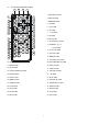
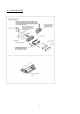
1.4 Locations and Names of the Controls
6
4
1
5
20 21
310 11
713 14
8
3 22
16
15
9
12
2
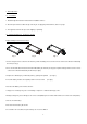
The figure of the Unit Chassis Facet After removing the Front Panel
The figure of the front panel
18
19
17
SD
AV IN
MIC
SHIFT
1
INT
2
3
RPT
4
RDM
5
-10
6
+10
UP
DN
MODE
TA
AF
BND APS
VOL
SEL
/MU
1.POWER/MUTE BUTTON
2. MODE BUTTON
3. UP / DN BUTTONS
4. SEL/VOL BUTTON
5. LCD
6. REL BUTTON
7. BAND BUTTON
8. APS BUTTON
9.1/PLAY/PAUSE BUTTON
10. 2/INT BUTTON
11. 3/RPT BUTTON
12. 4/RDM BUTTON
13. 5/-10 BUTTON
14. 6/+10 BUTTON
15. AV IN JACK
16. USB JACK
17. Card slot
18. RESET BUTTON
19. LED indicator
20. TA/AF BUTTON
21. IR Remote Sensor
22. Microphone