
Electric Heater User Manual


NOTE: DIAGRAMS & ILLUSTRATIONS NOT TO SCALE.
14
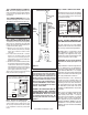
SIT Millivolt Gas Valve Controls
H
I
L
O
W
TPTH TP TH
P
I
L
O
T
P
I
L
O
T
O
N
it
O
F
F
HI / LO Knob
Variable Flame Height Adjustment
Manifold Pressure Port
Inlet
Pressure
Port
Main Gas
Control Knob
Piezo Igniter
IN
OUT
Figure 30
Step 13. TEST ALL CONNECTIONS FOR
LEAKS (FACTORY AND FIELD).
Test For Gas Leaks
A. Mix a 50% dish soap, 50% water solu-
tion.
B. Light the appliance (refer to the lighting
instructions provided in the Homeowner's
Care and Operation Instructions).
C. Brush all joints and connections with the
soapy water solution to check for leaks. If
bubbles are formed, or gas odor is detected,
turn the gas control knob to the “OFF” posi-
tion and close the gas shut-off valve. Either
tighten or refasten the leaking connection
and retest as described above.
D. When the gas lines are tested and leak free,
observe the individual tongues of fl ame on
the burner. Make sure all ports are open and
producing fl ame evenly across the burner. If
any ports are blocked, or partially blocked,
turn off unit, allow it to cool, then clean out
the ports.
Turn on gas supply and test for gas leaks
using a soapy water solution. Never use an
open fl ame to check for leaks.
Step 14. CHECKING APPLIANCE OPERA-
TION
With gas line installed run initial system
checkout before closing up the front of
the unit. Follow the pilot lighting instruc-
tions provided in the Homeowner's Care
and Operation Instructions (or pull out the
instruction label located in a holder on rear
shield of stove) . For piezo igniter location
see Figure 30.
Center
Top Twig
Right
Front Twig
Embers
Figure 28
DO NOT PLACE EMBERS ON TOP OF THE
BURNER SLOTS.
7. Install the center top twig onto the cor-
responding pin on the rear log and align it
with the indentation on front left log as shown
in Figure 26.
8. Install the front right twig onto the cor-
responding pin on the right front log. Align
the twig with the indentation on the front right
log as shown in Figure 27.
9. Place the glowing embers on the burner
as shown in Figures 28 & 29.
One package of ember material has been
included with this log set You will not need
to use the entire bag.
IMPORTANT: The quantity and placement of the
ember material can affect stove performance
therefore it is very important that it be placed
as shown in Figures
28 & 29.
a. Unpackage and divide the fi ne ember material
(mineral wool) into dime-sized fl uffy pieces.
b. Distribute the pieces over the top of the
front burner ports avoiding covering the slots
(see Figure 29) and fi lling the area in front of
the forward logs.
Figure 26
Figure 27
Figure 29
VERIFY THAT THE GAS LINE HAS BEEN
PURGED OF AIR (SEE STEP 10).
Figure 25
Left Top
Twig
Step 12. RE-INSTALL FRONT GLASS
ENCLOSURE PANEL
(Reverse instructions on Step 4)
Retrieve the front glass enclosure panel.
Visually inspect the gasket on the backside
of the frame. Gasket surface must be clean,
free of irregularities and seated fi rmly.
With the stove top off, position the glass front
enclosure panel into the front opening with
the gasket facing the relief door (reference
Figure 8 & 9). Let the bottom of the door
frame gently slide down, then hook the top
fl ange of the glass frame over the top of the
fi rebox frame.
Fasten the two latches located beneath the
fi rebox fl oor to the glass frame vee-fl ange.
Close both the latches securely.
Right Front Log
Figure 24
5. Install the right front log onto the cor-
responding burner pin and sub-fl oor right
tab as shown in Figure 24.
6. Install the left top twig onto the correspond-
ing pin on the rear log and align it with the
indentation on the front left log as shown in
Figure 25.