
Electric Heater User Manual


15
NOTE: DIAGRAMS & ILLUSTRATIONS NOT TO SCALE.
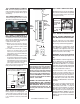
Figure 34
Adjustment Rod Up
(1/8" Open Position)
Air Shutter
Burner Tube
Adjusting Set Screw
Adjustment Rod Down
(full open position)
Figure 31
Burner
On/Off
Switch
Top View
Front
Burner Air Shutter Adjustment
Burner On/Off Switch
Burner Adjustment
WARNING: AIR SHUTTER ADJUSTMENT
SHOULD ONLY BE PERFORMED BY A
QUALIFIED PROFESSIONAL SERVICE
TECHNICIAN.
IMPORTANT: ENSURE THAT THE FRONT
GLASS PANEL IS IN PLACE AND SEALED
DURING ADJUSTMENT.
CAUTION: THE ADJUSTMENT ROD AND
NEARBY APPLIANCE SURFACES ARE
HOT. EXERCISE CAUTION TO AVOID
INJURY WHILE ADJUSTING FLAME
APPEARANCE.
Step 15. BURNER ADJUSTMENTS
Flame Appearance and Sooting
Proper fl ame appearance is a matter of taste.
Generally, most people prefer the warm glow
of a yellow to orange fl ame.
Appliances operated with air shutter openings
that are too large will exhibit fl ames that are
blue and transparent. These weak, blue and
transparent fl ames are termed anemic. If the
air shutter opening is too small sooting may
develop.
Air Shutter Adjustment Guidelines:
If the burner fl ame appearance differs greatly
from what is shown on this page (see Figure
33), some adjustment from standard for
the air shutter gap may be necessary (to
compensate for variables in the installation
and fuel such as, BTU value / composi-
tion, gas pressure, specifi c gravity of gas,
altitude, etc.).
The following chart is provided to aid you in
achieving the correct air shutter adjustment
for your installation.
SIT Millivolt Appliance Checkout
The pilot fl ame should be steady, not lifting
or fl oating. Flame should be blue in color
with traces of orange at the outer edge.
The top 3/8" (10 mm) at the pilot generator
(thermopile) and the top 1/8" minimum (tip)
of the quick drop out thermocouple should
be engulfed in the pilot fl ame. The fl ame
should project 1" (25 mm) beyond the hood
at all three ports (Figure 32).
Replace logs if removed for pilot inspection.
To light the burner, rotate the gas valve control
knob counterclockwise to the “ON” position
then turn “ON” the ON/OFF rocker switch.
MILLIVOLT
Thermocouple
Hood Igniter Rod
3/8" Min.
(9 mm)
Thermopile
Pilot
Nozzels
Figure 32 - Proper Pilot Flame Appearance
Figure 33 - Burner Flame Appearance
Air Shutter Adjustment Guidelines:
Amount of
Primary Air
Flame
Color
Air Shutter
Adjustment
If air shutter is
closed too far
Flame will
be yellow
Air shutter
gap should be
increased
If air shutter is
open too far
Flame will
be blue
Air shutter
gap should be
decreased
Table 10
When satisfi ed that the appliance operates
properly, proceed to fi nish the installation.
Leave the control knob in the ON position and
the on/off switch in the OFF position.
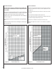
Main Burner Factory Air Shutter
Opening Setting - Inches (millimeter)
Model Natural
Gas
Propane
Gas
CI1500DVF
5/16"
(7.93 mm)
5/8"
(15.9 mm)
CI2500DVF
1/2"
(12.7 mm)
5/8"
(15.9 mm)
Initially, always position the air shutter to the
factory setting as shown in Figure 34 (adjust-
ment rod is located in the lower control area).
This can be done by moving the adjustment
rod up or down accordingly. Allow the burner
to operate for at least 15 minutes. Observe
the fl ame continuously. If it appears weak
or sooty as previously described, adjust the
air shutter to a more open position until the
desired fl ame appearance is achieved.
The adjustment rod and associated adjustable
air shutter is patented technology. Flame adjust-
ments can be made quickly and accurately to
taste without the need of disassembling the
appliance and waiting for 30 minutes after
each adjustment.
Sooting is indicated by black puffs developing
at the tips of very long orange fl ames. Sooting
results in black deposits forming on the logs,
appliance inside surfaces and on exterior
surfaces adjacent to the vent termination.
Sooting is caused by incomplete combus-
tion in the fl ames and lack of combustion air
entering the air shutter opening. To achieve
a warm yellow to orange fl ame that does not
soot, the shutter opening must be adjusted
between these two extremes.
No smoke or soot should be present. Repo-
sition the logs if fl ames impinge on any of
them. If the logs are properly positioned
and sooting conditions exist, the air shutter
opening on the main burner tube should be
adjusted. Normally, the more offsets in the
vent system, the greater the need for the air
shutter to be opened further.