
Electric Heater User Manual


5
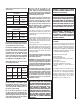
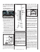
NOTE: DIAGRAMS & ILLUSTRATIONS NOT TO SCALE.
Top View / Corner Clearances
* Dimensions with a single asterix are reference dimensions only.
** If the optional warming shelves are installed, a greater alcove width is
required as follows:
CI1500DVF - 44" (1118 mm) min.
CI2500DVF - 52 1/2" (1334 mm) min.
***This includes any projections such as shelves, windowsills, mantels, etc.
above the appliance.
Note: Recommended clearance zone from the front of the appliance to combus-
tibles is 36 inches (914 mm) minimum
.
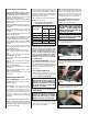
Floor Protection
When installed directly on carpeting, tile (see Note below) or other combustible material
other than wood fl ooring, the appliance shall be installed on a metal or wood panel extend-
ing the full width and depth of the stove body.
Note: Ceramic tile is non-combustible and does not require a wood or metal panel under
the appliance.
Vent Clearances - All Models
For Horizontal Sections:
Top - 3" (76.2 mm) min.
Sides - 1" (25.4 mm) min.
Bottom - 1" (25.4 mm) min.
For Vertical Sections:
Sides - 1" (25.4 mm) min.
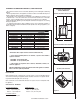
Top View / Rear Wall or Alcove Clearances
Side View / Rear Wall or Alcove Clearances
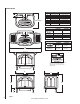
Clearance To Combustibles
& Alcove Dimensions
CLEARANCES
CI1500DVF
CI2500DVF
A (minimum)
*10” (254 mm)
B (minimum)
*14-1/4” (362 mm)
*17-1/4” (438 mm)
C (minimum)
*15-7/8” (403 mm)
*19” (483 mm)
D (minimum)
4” (102 mm)
4” (102 mm)
E (minimum)
2” (51 mm)
2” (51 mm)
F (minimum)
4” (102 mm)
4” (102 mm)
G (minimum)
0” (0 mm)
0” (0 mm)
H (minimum)
***62” (1575 mm)
***62” (1575 mm)
I (minimum)
**28 1/2” (724 mm)
**34 1/2” (876 mm)
J (MAXIMUM)
48” (1219 mm)
48” (1219 mm)
*10” (254 mm)
Figure 2
CLEARANCES TO COMBUSTIBLE MATERIALS / FLOOR PROTECTION
• The location should also be free of electrical, plumbing or other heating/air conditioning
ducting.
• Due to high temperatures, this appliance should be located out of traffi c and away from
furniture, draperies and not in windy or drafty areas.
• This appliance can be installed in most residential room confi gurations, parallel to a rear
or adjacent wall, or in an alcove that allows for the minimum clearances to combustible
surfaces. Your local building inspector should review your plans prior to installation.
• When installing this appliance, provide adequate clearances for the purposes of servicing
and proper operation.
• As determined through the safety certifi cation of this unit, a minimum clearance to
combustible materials must be maintained around specifi c areas of the gas appliance. (See
Table 5 & Figure 2)
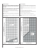
Table 5
H
D
*A
G
J
L E N N O X
*B
D
EE
I
F
F
*C
At Wall Firestops:
Top - 3" (76.2 mm) min.
Sides - 1" (25.4 mm) min.
Bottom - 1/2" (12.7 mm) min.