
Electric Heater User Manual


NOTE: DIAGRAMS & ILLUSTRATIONS NOT TO SCALE.
6
12
X
Roof Pitch is X/12
2 FT
MIN.
2 FT MIN.
Lowest
Discharge
Opening
H*
*H = MINIMUM HEIGHT FROM ROOF TO
LOWEST DISCHARGE OPENING OF VENT
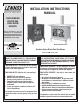
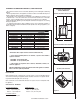
TERMINATION HEIGHTS FOR VENTS ABOVE
FLAT OR SLOPED ROOFS
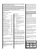
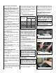
Horizontal Overhang
Vertical
Wall
Vent
Termination
Storm Collar
Concentric
Vent Pipe
Flashing
1 inch (25.4 mm) Minimum
Clearance to Combustibles
The vent/air intake termination clearances
above the high side of an angled roof is as
follows:
Roof Pitch ................. Feet Meters
Flat to 6/12 ................ 1.0 0.3
6/12 to 7/12 ............... 1.25 0.38
7/12 to 8/12 ............... 1.5 0.46
8/12 to 9/12 ............... 2.0 0.61
9/12 to 10/12 ............. 2.5 0.76
10/12 to 11/12 ........... 3.25 0.99
11/12 to 12/12 ........... 4.0 1.22
12/12 to 14/12 ........... 5.0 1.52
14/12 to 16/12 ........... 6.0 1.83
16/12 to 18/12 ........... 7.0 2.13
18/12 to 20/12 ........... 7.5 2.29
21/12 to 21/12 ........... 8.0 2.44
Figure 4
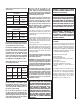
Figure 3
MANUFACTURED (MOBILE) HOME
REQUIREMENTS
These models may be installed in an after-
market permanently located, manufactured
home, where not prohibited by local codes.
When installed in Manufactured Housing
the following supplemental requirements
must be met:
• The appliance must be secured to the fl oor
(i.e. use (4) ¼” x 2 ¾” bolts and nuts or
equivalent. Note: Not included) for securing
appliance to the manufactured home fl oor.
• The appliance must be grounded to the
chassis of the manufactured home. Use a
No. 8 or heavier copper wire at least 18” in
length.
• The structural integrity of the manufactured
home fl oor, walls, ceiling and roof must be
maintained.
• A manufactured (mobile) home installation
must conform with the Manufactured Home
Construction and Safety Standard, Title 24
CFR, Part 3280, or, when such a stan-dard
is not applicable, the Standard for Manufac-
tured Home Installations, ANSI / NCSBCS
A225.1, or standard for Gas equipped
Recreational Vehicles and Mobile Housing,
CSA Z240.4.
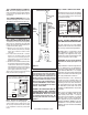
Horizontal Vent Termination Clearances
The horizontal vent termination must have
a minimum of 3" (76 mm) clearance to any
overhead combustible projection of 2 1/2" (64
mm) or less. See Figure 4. For projections
exceeding 2 1/2" (64 mm), For additional vent
location restrictions refer to Figure 5.
VENT TERMINATION CLEARANCES
Vertical Vent Termination Clearances
These instructions should be used as a
guideline and do not supersede local codes in
any way. Install vent according to local codes,
these instructions, the current National Fuel
Gas Code (ANSI-Z223.1) in the USA or the
current standards of CAN/CGA-B149.1 and
-B149.2 in Canada.
Side Elevation View
QUESTIONS TO ASK LOCAL BUILDING
OFFICIAL
This appliance must be installed per manu-
facturers’ instructions.
Installations must conform to appropriate
local codes and applicable state and federal
requirements. Familiarity with these require-
ments before installation is essential. Some
important considerations to discuss with
local building offi cials include:
1. Applicable codes (i.e. Uniform Mechanical
Code, State or Regional Gas Codes, National
Fuel Gas Code)
2. Local amendments
3. Recognized testing lab: OMNI-Test Labora-
tories Inc.; Beaverton, Oregon
4. Is a permit required - cost?
5. In some states or municipalities, a licensed
gas fi tter or plumber may be required to
install this appliance. Check with your local
building offi cial for requirements in your area
(i.e. Is a license required for installation of
gas supply line)?
6. Maximum amount of gas pipe without a
pressure test - type of test required?
7. Are below grade penetrations of the gas line
allowed?
8. Is concealed gas piping allowed?
9. Specifi c requirements of concealed fi t-
tings?
10. I s rigid pipe to appliance required?
11. Allowed piping materials?
12. Shut-off valve required within 4 feet of the
fi rebox?
13. M ay the shut-off valve be concealed?
14. Rooms where the installation is not
allowed?
In the absence of local codes, installation
should conform to National Fuel Gas Code,
ANSI Z223.1 / NFPA 54-Latest Edition in the
USA or National Fuel Gas Code, CAN/CGA-
B149-Latest Edition in Canada.
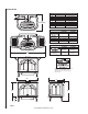
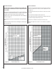
3"
(76 mm)
12"
(305 mm)
Horizontal T
Combustible Projection
greater than 2 1/2 inches in length
Horizontal Vent Termination Clearances
Combustible Projection
2 1/2 inches or less in length
18"
(457 mm)
Ventilated
Soffit
Unventilated
Soffit
ermination Kit
3"
(76 m
1"
(25 mm
Note - See vent manufacturer's instructions for recess
allowances, into exterior walls for the horizontal termi-
nation caps.