
Outdoor Fireplace User Manual

10
NOTE: DIAGRAMS & ILLUSTRATIONS NOT TO SCALE.
FIELD WIRING
Caution: Label all wires prior to disconnection
when servicing controls. Wiring errors can
cause improper and dangerous operation.
Verify proper operation after servicing.
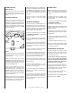
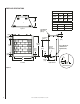
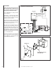
Refer to Figure 10 for the wiring schematic
for these fireplaces.
This fireplace is completely wired internally.
On the right hand side of the fireplace, at the
rear, are four (4) wires required to connect the
Battery and switch for operation.
Two brown wires are for the connection of the
switch. These are labeled SW and SW. A black
and red pair are for connection to the battery
pack. These are labeled (+) and (–).
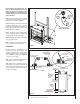
These wires are for low voltage current. An
electrical box has been provided to contain both
the switch and battery pack. Mount the box in
an appropriate location within the length of the
wiring provided. Feed all four wires through
one of the lower inlets to the box. Connect the
switch wires to the switch and the corresponding
(+), (–) to the battery holder.
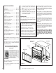
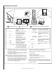
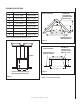
Install two D-cell batteries (not provided) and
test the switch before closing the switch box
(refer to Figure 11 ). The igniter should spark
to the pilot when the switch is on.
Figure 10
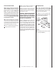
Figure 11
Switch
Cover
Weather Seal
Orient Batteries Vertically
To Fit Within Box
INTERMITTENT ELECTRONIC WIRING DIAGRAM
BROWN
BROWN
BLACK
BATTERY
WALL SWITCH BOX
BLACK (SENSOR)
BLACK (IGNITOR)
SPARK TO PILOT IGNITOR
IGNITOR MODULE
3V
RED
PILOT
IN
OUT
VENT
LO
HI
TH
TP
TH
TP
IN
ORANGE (THTP)
BLACK (TP)
GREEN (TH)
LIMIT
SWITCH
UMBILICAL CORD (9 Feet)