
Outdoor Fireplace User Manual

NOTE: DIAGRAMS & ILLUSTRATIONS NOT TO SCALE.
3
evlaVsaGdetaludoM-yllaunaMhtiwsledoM
saGlarutaN saGenaporP
.oNledoM
tupnI
etar
)H/UTB(
.oNledoM
tupnI
etar
)H/UTB(
GDO63E
000,05
ot
005,93
GDO63E
000,64
ot
000,73
GDO24E
000,05
ot
005,93
GDO24E
000,64
ot
000,73
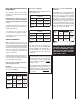
Table 2
Inlet Gas Supply Pressure
(all models)
Fuel # Minimum Maximum
Natural Gas
5.0" WC
(1.24 kPa)
10.5" WC
(2.61 kPa)
Propane
11.0" WC
(2.74 kPa)
13.0" WC
(3.23 kPa)
Manifold Gas Supply Pressure
(all models)
Fuel # Low High
Natural Gas
(Lo) 2.2" WC
(.55 kPa)
(Hi) 3.5" WC
(.87 kPa)
Propane
(Lo) 6.3" WC
(1.57 kPa)
(Hi) 10.0" WC
(2.49 kPa)
Table 3
Table 4
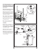
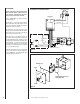
Test gage connections are provided on the
front of the gas control valve identified IN for
the inlet and OUT for the manifold side. A
1/8" NPT Test gauge connection is provided at
the inlet and outlet side of the electronic gas
control valve.
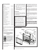
All Models -
All models have a manually modulated gas valve.
Input is shown in Table 1:
Gas Pressure - All Models
Tables 2 and 3 show the appliances' inlet and
manifold gas pressure.
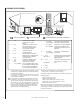
GENERAL INFORMATION
Note: Installation and repair should be per-
formed by a qualified service person. The appli-
ance should be inspected annually by a qualified
professional service technician. More frequent
inspections and cleanings may be required due
to yard care, insects, etc. It is imperative that
the control compartment and burners of the
appliance be kept clean.
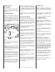
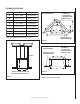
Provide adequate clearances around air open-
ings and adequate accessibility clearance for
service and proper operation. Never obstruct
the front openings of the appliance.
These appliances are designed to operate on
natural or propane gas only.
WARNING: PROPANE TANKS ARE AT
PRESSURES THAT WILL CAUSE DAM-
AGE TO VALVE COMPONENTS. VERIFY
THAT THE TANKS HAVE STEP DOWN
REGULATORS TO REDUCE THE PRES-
SURE TO SAFE LEVELS.
Table 1
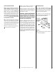
These appliances must be isolated from the
gas supply piping system (by closing their
individual manual shut-off valve) during any
pressure testing of the gas supply piping
system at test pressures equal to or less than
1/2 psig (3.5 kPa).
These appliances and their individual shut-off
valves must be disconnected from the gas sup-
ply piping system during any pressure testing
of that system at pressures greater than 1/2
psig (3.5 kPa).
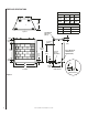
Orifice Sizes - Sea Level To High Altitude
(All Models)
These appliances are tested and approved for
installation at elevations of 0-4500 feet (0-1372
meters) above sea level, using the standard
burner orifice (See Table 4 ). For elevations
above 4500 feet, contact your gas supplier or
qualified service technician. Install the appli-
ance according to the regulations of the local
authorities having jurisdiction and, in the USA,
the National Fuel Gas Code NFPA 54 / ANSI
Z223.1 - latest edition or , in Canada, the CAN1-
B149.1 and .2 codes - latest edition.
Model
No.
Orifice size
Elevation
Feet
(meters)
Natural
Gas
Propane
E36ODG
0.1405"
(#28)
0.0785"
(#47)
0-4500
(0-1372)
E42ODG
0.1405"
(#28)
0.0785"
(#47)
NEW YORK AND MASSACHUSETTS
REQUIREMENTS
These appliances may be installed in the
following USA locations with the following
requirements:
Installation of these appliances are approved
for installation in the US state of Massachu-
setts if the following additional requirements
are met -
• Installation and repair must be done by a
plumber or gas fitter licensed in the Common-
wealth of Massachusetts.
• The flexible gas line connectors shall not
exceed 36 inches (92 centimeters) in length.
• The individual manual shut-off must be a
t-handle type valve.