
Stove User Manual


8
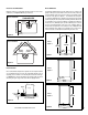
NOTE: DIAGRAMS & ILLUSTRATIONS ARE NOT TO SCALE.
Dimensions
The gas line screws into the gas valve at the back of the stove 5” in from
the right side of the stove and 4-3/16” up from the base of the unit.
Preparing Your Stove For Installation
Read all instructions before beginning your installation. If instructions
have not been read carefully, your installation could void your warranty
and may create a serious fire, health, or other safety hazard.
The Lennox Hearth Products warranty will be voided if one of the fol-
lowing occurs:
• Installation of any damaged stove or vent system component.
• Unauthorized modification of the direct-vent system.
• Installation other than as instructed by Lennox Hearth Products,
Security Chimneys™, or Simpson Dura-Vent.
• Installation of any stove or vent system component not manufac-
tured or approved by Lennox Hearth Products, Security Chimneys™,
or Simpson Dura-Vent.
When planning the installation for this appliance, it’s necessary to con-
sider the following:
• Where the unit is to be installed
• The vent system configuration to be used
• Gas supply (NG or LP)
• Electrical wiring
• Optional accessories (blower, wall-mounted or remote thermostat,
cast-iron panels or stove panel inserts)
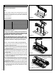
Top View
Front View
Figure 2
Figure 3
Side View
Figure 1
Pipe Clearances
All installations using a vertical termination cap must maintain one inch
clearance between the direct-vent pipe and combustibles. For horizontal
runs of pipe, one inch of clearance to combustibles on the sides and
bottom and two inches on the top of the pipe is required. See Pages 14,
15 and 16 for allowable pipe configurations.
21-3/8”
(543mm)
24-5/8”
(626mm)
C/L
Flue Collar
4” Inner / 6-5/8” Outer
14-3/4”
(375mm)
22-1/2”
(572mm)
27-3/8”
(695mm)