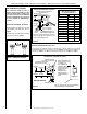
INSTALLATION INSTRUCTIONS MLDVT Direct-Vent Gas Fireplaces MODELS P/N 506015-02 Rev. E 06/2011 This manual is one of a set of two supporting this product. Refer to P/N 506017-01 for Care and Operation Instructions. Ce manuel est disponible en francais, simplement en faire la demande. Numéro de la pièce 506223-03. MILLIVOLT: MLDVT-30NM MLDVT-30PM MLDVT-35NM MLDVT-35PM INSTALLER: Leave this manual with the appliance. CONSUMER: Retain this manual for future reference.
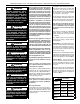
LENNOX HEARTH PRODUCTS • MERIT® SERIES DIRECT-VENT GAS FIREPLACES • MODELS MLDVT-30/35/40/45 • INSTALLATION INSTRUCTIONS PACKAGING TABLE OF CONTENTS Packaging..........................................Page Introduction.......................................Page General Information...........................Page Requirements for the Commonwealth of Massachusetts..Page New York City Approval......................Page Cold Climate Insulation......................Page Manufactured Home Requirements...
LENNOX HEARTH PRODUCTS • MERIT® SERIES DIRECT-VENT GAS FIREPLACES • MODELS MLDVT-30/35/40/45 • INSTALLATION INSTRUCTIONS WARNING Improper installation, adjustment, alteration, service or maintenance can cause injury or property damage. Refer to this manual. For assistance or additional information consult a qualified installer, service agency or the gas supplier.
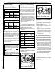
LENNOX HEARTH PRODUCTS • MERIT® SERIES DIRECT-VENT GAS FIREPLACES • MODELS MLDVT-30/35/40/45 • INSTALLATION INSTRUCTIONS Maximum Natural Gas 4.5" WC (1.12 kPa) 10.5" WC (2.61 kPa) Propane 11.0" WC (2.74 kPa) 13.0" WC (3.23 kPa) Table 2 Manifold Gas Supply Pressure (all models) Fuel # Low High Natural Gas (Lo) 2.2" WC (0.55 kPa) (Hi) 3.5" WC (0.87 kPa) Propane (Lo) 6.3" WC (1.57 kPa) (Hi) 10.0" WC (2.
LENNOX HEARTH PRODUCTS • MERIT® SERIES DIRECT-VENT GAS FIREPLACES • MODELS MLDVT-30/35/40/45 • INSTALLATION INSTRUCTIONS APPLICATION TOP VENT TOP VENT APPLICATION Note: When the unit is installed with one side flush with a wall, the wall on the other side of the unit must not extend beyond the front edge of the unit.
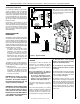
LENNOX HEARTH PRODUCTS • MERIT® SERIES DIRECT-VENT GAS FIREPLACES • MODELS MLDVT-30/35/40/45 • INSTALLATION INSTRUCTIONS Vent Termination Clearances These instructions should be used as a guideline and do not supersede local codes in any way. Install venting according to local codes, these instructions, the current National Fuel Gas Code (ANSI-Z223.1) in the USA or the current standards of CAN/CSA-B149.1 in Canada.
LENNOX HEARTH PRODUCTS • MERIT® SERIES DIRECT-VENT GAS FIREPLACES • MODELS MLDVT-30/35/40/45 • INSTALLATION INSTRUCTIONS Exterior HORIZONTAL Vent TERMINATION Clearance Requirements NOTE: Local Codes Or Regulations May Require Different Clearances. * See Item D in the Text Below. P N NOTE: Location Of The Vent Termination Must Not Interfere With Access To The Electrical Service.
LENNOX HEARTH PRODUCTS • MERIT® SERIES DIRECT-VENT GAS FIREPLACES • MODELS MLDVT-30/35/40/45 • INSTALLATION INSTRUCTIONS MINIMUM CLEARANCES TO COMBUSTIBLES Appliance And Vent Clearances Combustible Shelf Height - Inches (millimeters) Model No.
LENNOX HEARTH PRODUCTS • MERIT® SERIES DIRECT-VENT GAS FIREPLACES • MODELS MLDVT-30/35/40/45 • INSTALLATION INSTRUCTIONS WARNING Failure to position the parts in accordance with these diagrams or failure to use only parts specifically approved with this appliance may result in property damage or personal injury.
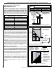
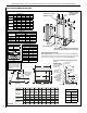
LENNOX HEARTH PRODUCTS • MERIT® SERIES DIRECT-VENT GAS FIREPLACES • MODELS MLDVT-30/35/40/45 • INSTALLATION INSTRUCTIONS FIREPLACE AND FRAMING SPECIFICATIONS Framing Vent Framing - Top Vent With One 90° Elbow Framing Dimensions Model No. MLDVT-30 MLDVT-35 MLDVT-40 MLDVT-45 A B C D in. 30-1/4 35-1/4 39-1/4 16 mm 768 895 997 406 in. 35-1/4 35-1/4 39-1/4 16 mm 895 895 997 406 in. 40-1/4 40-1/4 44-1/4 16 mm 1022 1022 1124 406 in.
LENNOX HEARTH PRODUCTS • MERIT® SERIES DIRECT-VENT GAS FIREPLACES • MODELS MLDVT-30/35/40/45 • INSTALLATION INSTRUCTIONS fireplace FRAMING specifications Model No. A B C D E in. 30 1/4 53 3/16 37 29/32 26 13/16 12 1/4 MLDVT-30 mm 768 1350 963 681 311 in. 35 1/4 57 1/2 40 5/8 28 3/4 13 3/4 MLDVT-35 MLDVT-40 MLDVT-45 E 7 (178) mm 1461 730 1032 895 349 in. 40 1/4 61 13/16 43 11/32 30 11/16 15 1/8 mm 1022 1554 384 1101 779 in.
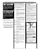
LENNOX HEARTH PRODUCTS • MERIT® SERIES DIRECT-VENT GAS FIREPLACES • MODELS MLDVT-30/35/40/45 • INSTALLATION INSTRUCTIONS Step 3. Install the Vent System Installation of Vent Restrictor General Information A vent restrictor may be needed with this appliance. The restrictor is installed in the appliance top flue outlet as shown in Figure 16, either before adding vent, from above, or after installation of vent from below, within the firebox. The restrictor is self securing through a positive friction fit.
LENNOX HEARTH PRODUCTS • MERIT® SERIES DIRECT-VENT GAS FIREPLACES • MODELS MLDVT-30/35/40/45 • INSTALLATION INSTRUCTIONS Vertical Termination Systems (Roof) See Figure 17 on Page 13 and Figures 25 through 27 on Pages 16 and 17 and their associated Vertical Vent Tables which illustrate the various vertical venting configurations that are possible for use with these appliances. Secure Vent™ pipe applications are shown in these Figures; Secure Flex™ pipe may also be used.
LENNOX HEARTH PRODUCTS • MERIT® SERIES DIRECT-VENT GAS FIREPLACES • MODELS MLDVT-30/35/40/45 • INSTALLATION INSTRUCTIONS Vertical (Offset) Installation Analyze the vent routing and determine the quantities of vent sections and number of elbows required. Refer to Vertical Vent Figures and Tables on Pages 16 and 17 to select the type of vertical installation desired. Vent sections are available in net lengths of 4-1/2" (114 mm), 10-1/2" (267 mm), 22-1/2" (572 mm), 34-1/2" (876 mm) and 46-1/2" (1181 mm).
LENNOX HEARTH PRODUCTS • MERIT® SERIES DIRECT-VENT GAS FIREPLACES • MODELS MLDVT-30/35/40/45 • INSTALLATION INSTRUCTIONS One method of support is by utilizing field provided support straps (conventional plumber’s tape). Secure the plumber’s tape to the framing members with nails or screws. Loop the tape around the vent, securing the ends of the tape to the framing. If desired, sheet metal screws #6 x 1/2" length may be used to secure the support straps to the vent pipe. Refer to Figure 20. F.
LENNOX HEARTH PRODUCTS • MERIT® SERIES DIRECT-VENT GAS FIREPLACES • MODELS MLDVT-30/35/40/45 • INSTALLATION INSTRUCTIONS VERTICAL VENT FIGURES/TABLES Table A Notes: • Secure Vent™ (rigid vent pipe) is shown in the Figures; Secure Flex™ (flexible vent pipe) may also be used.
LENNOX HEARTH PRODUCTS • MERIT® SERIES DIRECT-VENT GAS FIREPLACES • MODELS MLDVT-30/35/40/45 • INSTALLATION INSTRUCTIONS VERTICAL VENT FIGURES/TABLES (continued) Example: If 20 feet total (H+H1) horizontal vent run is needed, then 4 feet minimum of (V) vertical vent will be required. Table B V Minimum H + H1 Maximum feet (meter) feet (meter) 5 (1.524) 5 (1.524) 1 (0.305) 10 (3.048) 2 (0.610) 15 (4.572) 3 (0.914) 20 (6.096) 4 (1.219) This table shows a 1(V) to 5(H) ratio.
LENNOX HEARTH PRODUCTS • MERIT® SERIES DIRECT-VENT GAS FIREPLACES • MODELS MLDVT-30/35/40/45 • INSTALLATION INSTRUCTIONS Building Support Framing Support Brackets TYPICAL HORIZONTAL VENT INSTALLATION Horizontal / Inclined Run Typical Termination Shown SV4.5E90 Elbow Ceiling SV4.5L6/12/24/36/48 Vent Sections u Firestop / Spacer Vertical Rise SV4.5VF Exterior Wall Support Bracket Spacing Every 5 ft (1.52 m) u When Using Secure Flex™, Use Firestop / Spacer SF4.
LENNOX HEARTH PRODUCTS • MERIT® SERIES DIRECT-VENT GAS FIREPLACES • MODELS MLDVT-30/35/40/45 • INSTALLATION INSTRUCTIONS J. Assemble vent run to exterior wall - If not previously measured, locate the center of the vent at the exterior wall. Prepare an opening as described in Step B. Assemble the vent system to point where the terminus of the last section is located relative to the exterior surface to which the termination is to be attached as shown in Figure 30 and Table 8.
LENNOX HEARTH PRODUCTS • MERIT® SERIES DIRECT-VENT GAS FIREPLACES • MODELS MLDVT-30/35/40/45 • INSTALLATION INSTRUCTIONS Use Table 8 as an aid in venting component selection for a particular range of exterior wall thicknesses. Venting Components Required for Various Exterior Wall Thicknesses, when using Typical Termination Kits Vent Components Required Termination Kit Only H Maximum Exterior Wall Thickness - inches (mm) 6 to 9-1/4 (152 to 235) 2.5 10-3/4 to 14 (273 to 356) Termination Kit and 12 in.
LENNOX HEARTH PRODUCTS • MERIT® SERIES DIRECT-VENT GAS FIREPLACES • MODELS MLDVT-30/35/40/45 • INSTALLATION INSTRUCTIONS HORIZONTAL VENT FIGURES / TABLES (continued) Wall Firestop/Spacer Table E (SV4.5HF) H + H1 Maximum H H1 V Note - When using Secure FlexTM, use Firestop/Spacer SF4.5VF. When using Secure Flex, Wall Firestop/Spacer (SV4.5HF) use Firestop/Spacer SF4.5HF. feet (meter) 3 (0.914) V Minimum feet (meter) Elbow Only 5 (1.524) 1 (0.305) 10 (3.048) 2 (0.610) 15 (4.
LENNOX HEARTH PRODUCTS • MERIT® SERIES DIRECT-VENT GAS FIREPLACES • MODELS MLDVT-30/35/40/45 • INSTALLATION INSTRUCTIONS HORIZONTAL VENT FIGURES / TABLES (continued) Table F Typical termination shown. TM, use Firestop/Spacer SF4.5VF. When using Secure Flex, use Firestop/Spacer SF4.5HF. H1 Ceiling Firestop/Spacer (SV4.5VF) (SV4.5HF) feet (meter) 5 (1.524) feet (meter) Elbow Only 5 (1.524) 1 (0.305) 10 (3.048) 2 (0.610) 15 (4.572) 3 (0.914) 20 (6.096) 4 (1.
LENNOX HEARTH PRODUCTS • MERIT® SERIES DIRECT-VENT GAS FIREPLACES • MODELS MLDVT-30/35/40/45 • INSTALLATION INSTRUCTIONS Vertical or Horizontal Venting Using Secure Flex™ Kits and Components Secure Flex™ venting kits and components may be used in any venting application in place of rigid Secure Vent™ (SV4.5) direct-vent components. All restrictions, clearances and allowances that pertain to the rigid piping apply to the flexible venting.
LENNOX HEARTH PRODUCTS • MERIT® SERIES DIRECT-VENT GAS FIREPLACES • MODELS MLDVT-30/35/40/45 • INSTALLATION INSTRUCTIONS Step 4. Field Wiring CAUTION Ground supply lead must be connected to the wire attached to the green ground screw located on the outlet box. See Figure 38. Failure to do so will result in a potential safety hazard. The appliance must be electrically grounded in accordance with local codes or, in the absence of local codes, the National Electrical Code, ANSI/NFPA 70-latest edition.
LENNOX HEARTH PRODUCTS • MERIT® SERIES DIRECT-VENT GAS FIREPLACES • MODELS MLDVT-30/35/40/45 • INSTALLATION INSTRUCTIONS 7. If wall-mounted ON/OFF control or thermostat is to be used, mount it in a convenient location on a wall near the fireplace.
LENNOX HEARTH PRODUCTS • MERIT® SERIES DIRECT-VENT GAS FIREPLACES • MODELS MLDVT-30/35/40/45 • INSTALLATION INSTRUCTIONS Step 6. Connecting Gas Line Gas Flex Line Connector All codes require a shut-off valve mounted in the supply line. The orientation of the shut-off valve should face the front. Figure 40 illustrates two methods for connecting the gas supply. A Sediment Trap is recommended to prevent moisture and debris in gas line from damaging the valve. The flex-line method is acceptable in the U.S.A.
LENNOX HEARTH PRODUCTS • MERIT® SERIES DIRECT-VENT GAS FIREPLACES • MODELS MLDVT-30/35/40/45 • INSTALLATION INSTRUCTIONS TEST ALL CONNECTIONS FOR GAS LEAKS (FACTORY AND FIELD) WARNING Never use an open flame to check for leaks. Turn on gas supply and test for gas leaks, using a gas leak test solution (also referred to as bubble leak solution).
LENNOX HEARTH PRODUCTS • MERIT® SERIES DIRECT-VENT GAS FIREPLACES • MODELS MLDVT-30/35/40/45 • INSTALLATION INSTRUCTIONS Step 8. INSTALL VOLCANIC STONE, GLOWING EMBERS, AND LOGS Separate into Quarter Size (separate) Pieces NOTE: Turn off all electricity to the appliance before you install volcanic stone, embers and logs. 1. Remove the front glass enclosure panel (see Removing Glass Enclosure Panels on Page 31). 2. Locate log set, embers and volcanic stone. Handle logs carefully to prevent breakage. 3.
LENNOX HEARTH PRODUCTS • MERIT® SERIES DIRECT-VENT GAS FIREPLACES • MODELS MLDVT-30/35/40/45 • INSTALLATION INSTRUCTIONS MLDVT-30 & MLDVT-35 Log Placement (model-35 shown; model-30 similar) 4 Log Number 5 1 Description 1 2 3 4 5 Rear Log Left Front Log Right Front Log Left Cross Log Right Cross Log Catalog Number for the entire log set: MLDVT-30: H7839 MLDVT-35: H7666 3 2 Left Rear Log Bracket Position against the right Right Rear Log Bracket Volcanic Stone Log Rack Glowing Embers (Do not place
LENNOX HEARTH PRODUCTS • MERIT® SERIES DIRECT-VENT GAS FIREPLACES • MODELS MLDVT-30/35/40/45 • INSTALLATION INSTRUCTIONS MLDVT-40 & MLDVT-45 Log Placement (model-40 shown; model-45 similar) 5 1 4 Log Number 1 2 3 4 5 Description Rear Log Left Front Log Right Front Log Left Cross Log Right Cross Log Catalog Number for the entire log set: MLDVT-40: H7667 MLDVT-45: H7840 3 2 Position on the left rear log bracket 1 Right Rear Log Bracket Volcanic Stone Glowing Embers Log Rack (Do not place glowing em
LENNOX HEARTH PRODUCTS • MERIT® SERIES DIRECT-VENT GAS FIREPLACES • MODELS MLDVT-30/35/40/45 • INSTALLATION INSTRUCTIONS Step 9. INSTALLATION AND REMOVAL OF GLASS DOOR WARNING • Do not attempt to substitute the materials used on these doors, or replace cracked or broken glass. • Handle this glass with extreme care! Glass is susceptible to damage; do not scratch or handle roughly while reinstalling the glass door frame.
LENNOX HEARTH PRODUCTS • MERIT® SERIES DIRECT-VENT GAS FIREPLACES • MODELS MLDVT-30/35/40/45 • INSTALLATION INSTRUCTIONS Burner Air Shutter Adjustment Procedure Adjustment Set-Screw WARNINGS • Air shutter adjustment should only be performed by a qualified professional service technician. • Ensure front glass panel are in place and sealed during adjustment. CAUTIONS Burner Tube Adjustment Rod Up (closed min. position) Air Shutter Adjustment Rod Down (fully open air opening position) Ref.
LENNOX HEARTH PRODUCTS • MERIT® SERIES DIRECT-VENT GAS FIREPLACES • MODELS MLDVT-30/35/40/45 • INSTALLATION INSTRUCTIONS Step 11. HOOD INSTALLATION (Refer to Figure 53) All models must have a hood installed prior to operating. Install hood by sliding it into the slots on the lower edge of the cabinet top. FINISHING REQUIREMENTS - Wall Details Complete finished interior wall.
LENNOX HEARTH PRODUCTS • MERIT® SERIES DIRECT-VENT GAS FIREPLACES • MODELS MLDVT-30/35/40/45 • INSTALLATION INSTRUCTIONS Step 12. ATTACHING SAFETY-IN-OPERATION WARNINGS It is the installer’s responsibility to ensure these warnings are properly affixed during installation. These warning labels are a critical step in informing consumers of safe operation of this appliance.
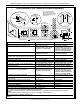
LENNOX HEARTH PRODUCTS • MERIT® SERIES DIRECT-VENT GAS FIREPLACES • MODELS MLDVT-30/35/40/45 • INSTALLATION INSTRUCTIONS Installation Accessories Listed Secure Vent™ Components Cat. No. H1968 94L10 Model SV4.5HT-2 SV4.5HTSS Description Horizontal Square Termination with Firestop/ Spacer (H2246) & Adaptor (74L61) Cat. No. Model Vent Sections 77L70 SV4.5L6 6 Inch (152 mm) (Rigid) 77L71 SV4.5L12 12 Inch (305 mm) 77L72 SV4.5L24 24 Inch (610 mm) 77L73 SV4.5L36 36 Inch (914 mm) 77L74 SV4.
LENNOX HEARTH PRODUCTS • MERIT® SERIES DIRECT-VENT GAS FIREPLACES • MODELS MLDVT-30/35/40/45 • INSTALLATION INSTRUCTIONS INSTALLATION ACCESSORIES CONTINUED Cat. # Model Description H1969 SF4.5HT-2 Horizontal Square Termination for flex (without flex) 77L87 SFKIT12S Square Term. for flex (with 12 inch [305 mm]* compressed flex) 77L88 SFKIT18S Square Term. for flex (with 18 inch [457 mm]* compressed flex) 77L89 SFKIT24S Square Term.
LENNOX HEARTH PRODUCTS • MERIT® SERIES DIRECT-VENT GAS FIREPLACES • MODELS MLDVT-30/35/40/45 • INSTALLATION INSTRUCTIONS Gas Conversion Kits Electronic DEXEN Systems Natural Gas To Propane Gas Conversion Kits WARNING This conversion kit shall be installed by a qualified service agency in accordance with the manufacturer’s instructions and all applicable codes and requirements of the authority having jurisdiction.
LENNOX HEARTH PRODUCTS • MERIT® SERIES DIRECT-VENT GAS FIREPLACES • MODELS MLDVT-30/35/40/45 • INSTALLATION INSTRUCTIONS Step 6. See Figure 57 and remove the pilot hood assembly to access the hexed pilot orifice. Remove and replace the orifice with the one provided with the kit.
LENNOX HEARTH PRODUCTS • MERIT® SERIES DIRECT-VENT GAS FIREPLACES • MODELS MLDVT-30/35/40/45 • INSTALLATION INSTRUCTIONS Step 8. See Figure 59 and replace the pilot orifice as follows: Remove pilot hood assembly to access the phillipped pilot orifice. Remove and replace the orifice with the one provided with the kit. Exercise extreme care to prevent damage to or breakage of the igniter assembly.
LENNOX HEARTH PRODUCTS • MERIT® SERIES DIRECT-VENT GAS FIREPLACES • MODELS MLDVT-30/35/40/45 • INSTALLATION INSTRUCTIONS Lennox Hearth Products reserves the right to make changes at any time, without notice, in design, materials, specifications, prices and also to discontinue colors, styles and products. Consult your local distributor for fireplace code information. Printed in U.S.A. © 2009 Lennox Hearth Products P/N 506015-02 Rev.