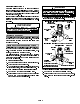
INSTALLATION INSTRUCTIONS £ PRODUCT LITERATURE ¤ 1998 Lennox Industries Inc. 9DOXH70 6HULHV Dallas, Texas $&% &RQGHQVLQJ 8QLWV &21'(16,1* 81,76 1--1/2 through 5 ton 503,800M 2/98 /LWKR 8 6 $ Supersedes 503,755M TABLE OF CONTENTS VALUE 10TM CONDENSING UNIT Value 10 condensing units are designed for expansion valve (TXV) and RFC systems. Refer to Lennox engineering handbook for expansion valve kits which must be ordered separately. SHIPPING AND PACKING LIST VALUE 10 CONDENSING UNIT . . . . . . .
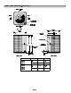
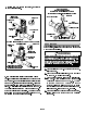
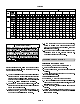
10ACB UNIT DIMENSIONS--INCHES (MM) INLET AIR INLET INLET AIR AIR INLET SUCTION LINE CONNECTION LIQUID LINE CONNECTION AIR TOP VIEW 24-1/4 (616) 24-1/4 (616) DISCHARGE OUTDOOR COIL FAN AIR COMPRESSOR B A SUCTION & LIQUID LINE CONNECTION ELECTRICAL INLETS 2-3/4 (70) 3/4 (19) SIDE VIEW SIDE VIEW Model No. 10ACB12 in. A B 25 24-1/4 635 616 33 32-1/4 838 819 10ACB18 10ACB24 10ACB30 10ACB36 10ACB42 mm in.
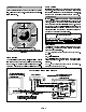
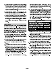
SETTING THE UNIT Roof Mounting Install unit at a minimum of 4 inches above the surface Refer to unit dimensions on page 2 for sizing mounting of the roof. Care must be taken to ensure weight of unit slab, platforms or supports. Refer to figure 1 for instal- is properly distributed over roof joists and rafters. Ei- lation clearances. ther redwood or steel supports are recommended. ELECTRICAL In the U.S.A.
PLUMBING NOTE -- Line length should be no greater than 50 feet (15.2 m). Select line set diameters from table 1 to en- Field refrigerant piping consists of liquid and suction lines from the condensing unit (sweat connections) to the indoor evaporator coil (flare or sweat connections). sure oil return to compressor.
Expansion Valve Systems '$1*(5 Expansion valves equipped with either Chatleff or Do not attempt to backseat this valve. Attempts to flare type fittings are available from Lennox. Refer to backseat this valve will cause snap ring to explode the indoor coil installation instructions or the engineer- from valve body under pressure of refrigerant. ing handbook for applicable expansion valves for use Personal injury and unit damage will result. with specific match--ups.
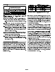
3-- Replace stem cap. Tighten finger tight, then tighten SUCTION LINE (BALL TYPE) SERVICE VALVE an additional 1/6 turn.
5 -- Connect the high pressure hose of the manifold tal actual pressure within a given volume or sys- gauge set to the service port of the suction valve. tem, above the absolute zero of pressure. Absolute (Normally, the high pressure hose is connected to pressure in a vacuum is equal to atmospheric pres- the liquid line port, however, connecting it to the sure minus vacuum pressure.
TABLE 3 67$57 83 IMPORTANT Crankcase heater (used on 3--1/2, 4 and 5 ton units) should be energized 24 hours before unit Liquid Line Ozs. per 5 ft. (ml per mm) adjust Set Diameter from 20 ft. (6.1m) line set* 5/16 in. (8mm) 2 ounce per 5 ft. 3/8 in. 3 ounce per 5 ft. (10mm) (85ml per 1.5m) (57ml per 1.5m) *If line length is greater than 20 ft. (6.1m), add this amount. If start--up to prevent compressor damage as a re- line length is less than 20 ft. (6.1m), subtract this amount.
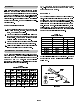
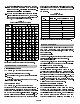
TABLE 4 NORMAL OPERATING PRESSURES IN PSIG (LIQUID AND SUCTION +/-- 10 PSIG)* OUT. COIL MODE ENTERING AIR TEMP. TXV 10ACB18 10ACB24 10ACB30 10ACB36 10ACB42 10ACB48 10ACB60 10ACB62 LIQ. SUC. LIQ. SUC. LIQ. SUC. LIQ. SUC. LIQ. SUC. LIQ. SUC. LIQ. SUC. LIQ. SUC. LIQ. SUC. 65 (18.3) 145 71 155 65 160 65 168 63 176 62 162 68 157 69 153 66 159 64 75 (23.9) 167 77 181 70 188 70 197 68 203 66 185 72 182 72 180 71 188 68 85 (29.
4-- Subtract the liquid line temperature from the satu- agree with the values given in table 6. If not, add refrig- ration temperature (according to the chart) to de- erant to lower the approach temperature or recover re- termine subcooling. (Saturation temperature -- frigerant from the system to increase the approach Liquid line temperature = Subcooling) temperature. TABLE 6 5-- Compare the subcooling value with those in table APPROACH METHOD 5. If subcooling is greater than shown, some refrigNO.
blocked or dirty coil. The low pressure switch (SPST, 3-- Check wiring for loose connections. NO) protects the system compressor from damage due 4-- Check for correct voltage at unit (unit operating). to loss of charge. The switch will trip at 15 +/-- 5 psig 5-- Check condenser fan motor amp--draw. (103 +/-- 34 kPa) and automatically resets at 25 +/--3 psig Unit nameplate _________ Actual ____________ . (172 +/-- 21 kPa).
67$57 83 $1' 3(5)250$1&( &+(&.